Arc tube and method of manufacturing same

a technology of arc tube and manufacturing method, which is applied in the manufacture of electrode systems, cold cathode manufacturing, electric discharge tube/lamps, etc., can solve the problems of emission color variation and arc tube service life reduction, emission color variation and emission color variation, and the efficiency of arc tube reduction

Inactive Publication Date: 2012-05-31
NGK INSULATORS LTD
View PDF1 Cites 1 Cited by
  • Summary
  • Abstract
  • Description
  • Claims
  • Application Information

AI Technical Summary

Benefits of technology

[0136]A continuous energization test was conducted on each of the arc tubes to measure a period of time (effective time during which the arc tube functions as a lamp) from the start of energization to the time when the brightness dropped to 80% of the brightness at the start of energization.
[0137]The ratios of the effective lamp times of Inventive Example 6 and Reference Examples 3, 4 to the effective lamp time h (hour) of Inventive Example 5 were checked.
[0138]Lamp efficiencies of Inventive Example 6 and Reference Examples 3, 4 were indicated as relative values with respect to the lamp efficiency 100 of Inventive Example 5.
[0139]The evaluation results are shown in Table 2.
[0140]It can be seen from the results shown in Table 2 that the ratio of the diameter of the distal end portion of the first el

Problems solved by technology

The process according to the related art for assembling the arc tube is problematic in that it requires an increased number of assembling steps because the electrodes need to be sealed by glass frit.
The arc tube according to the related art itself is disadvantageous for the following reasons: Since the two electrodes are inserted and sealed in the corresponding capillaries after the ceramic tube is fabricated, the inside diameter of each of the capillaries have to be larger than the maximum diameter of the electrodes, i.e., the diameter of their distal ends.
Therefore, as the capillaries tend to have different lengths, the distal ends of the electrodes tend to project from inner surfaces of the light emitting body by different distances, resulting in an emission color variation and a reduction in the arc tube service life due to the different distances from the inner surface of the light emitting body.
As the respective electrodes are positioned at the opposite ends of the ceramic tube, if the ceramic tube has a different overall length, the distance between the electrodes becomes different, resulting in a reduction in the efficiency of the arc tube and an emission color variation.
When the electrodes are sealed in the electrodes, the electrodes are l

Method used


Image

  • Arc tube and method of manufacturing same
  • Arc tube and method of manufacturing same
  • Arc tube and method of manufacturing same

Examples


first examples

[0106]Arc tubes fabricated according to Inventive Example 1, Inventive Example 2, and Comparative Example 1 were measured for cracks and leakages from the light emitting bodies. The arc tubes were confirmed for variations of the distal end position of the first electrode, i.e., variations of the distance from the ceramic wall surface to the distal end of the first electrode.

##ventive example 1

INVENTIVE EXAMPLE 1

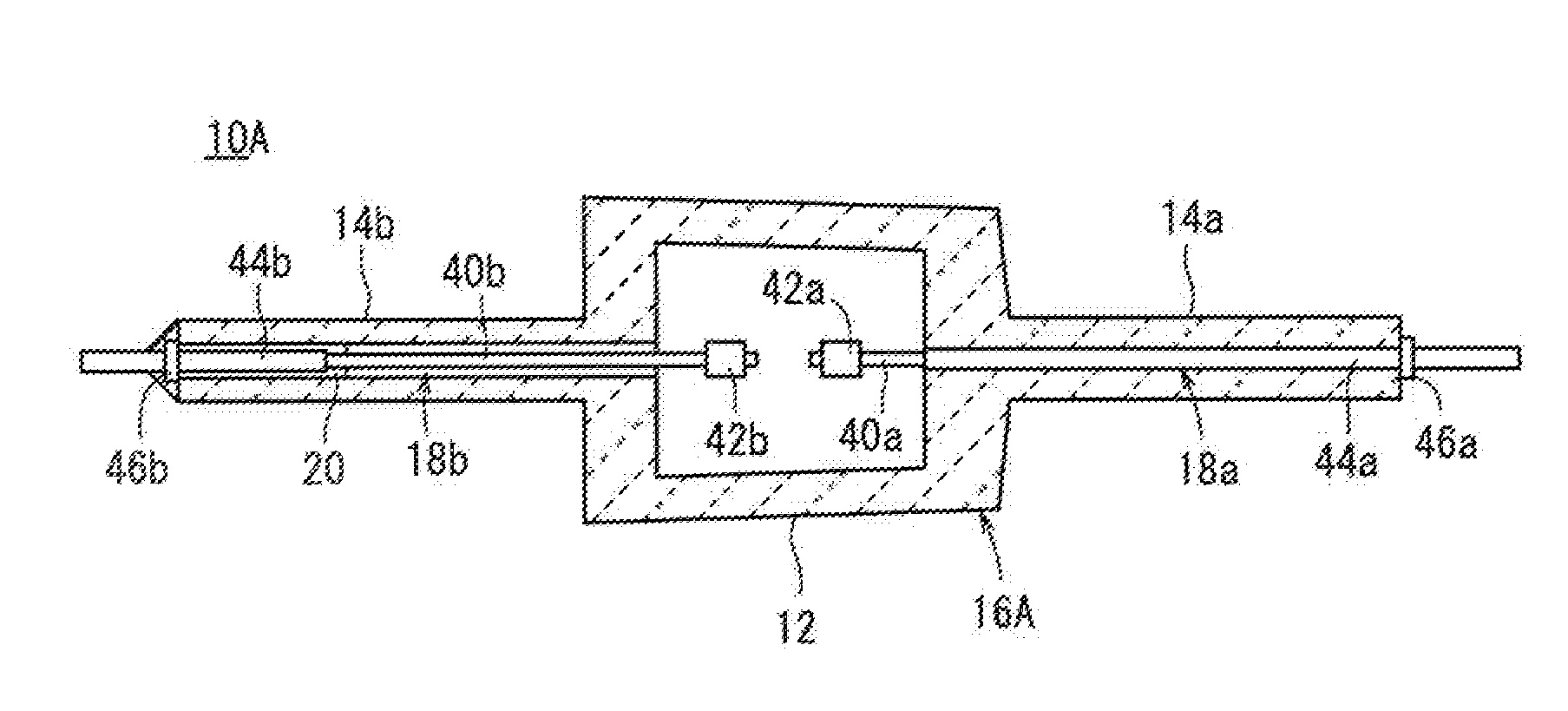
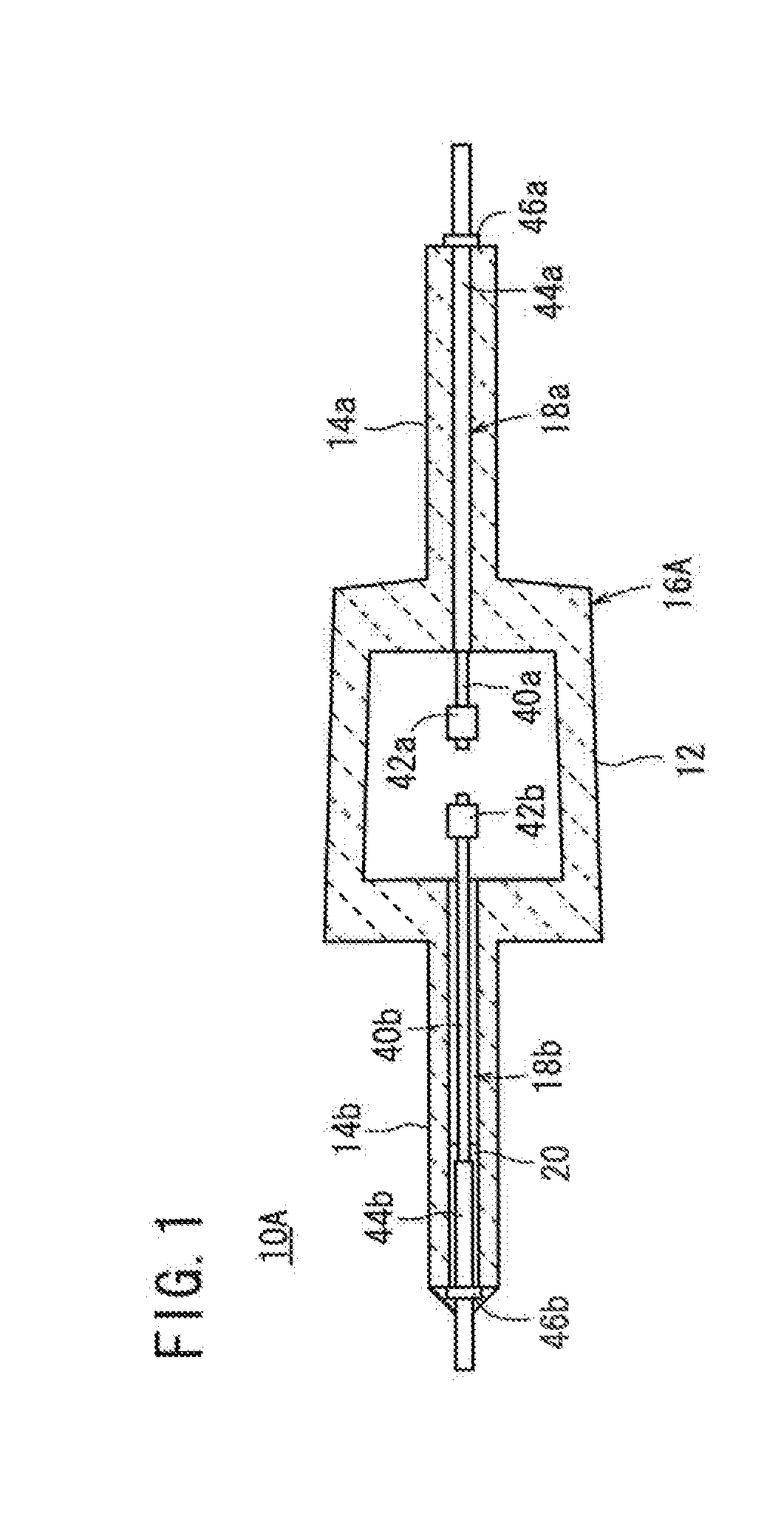
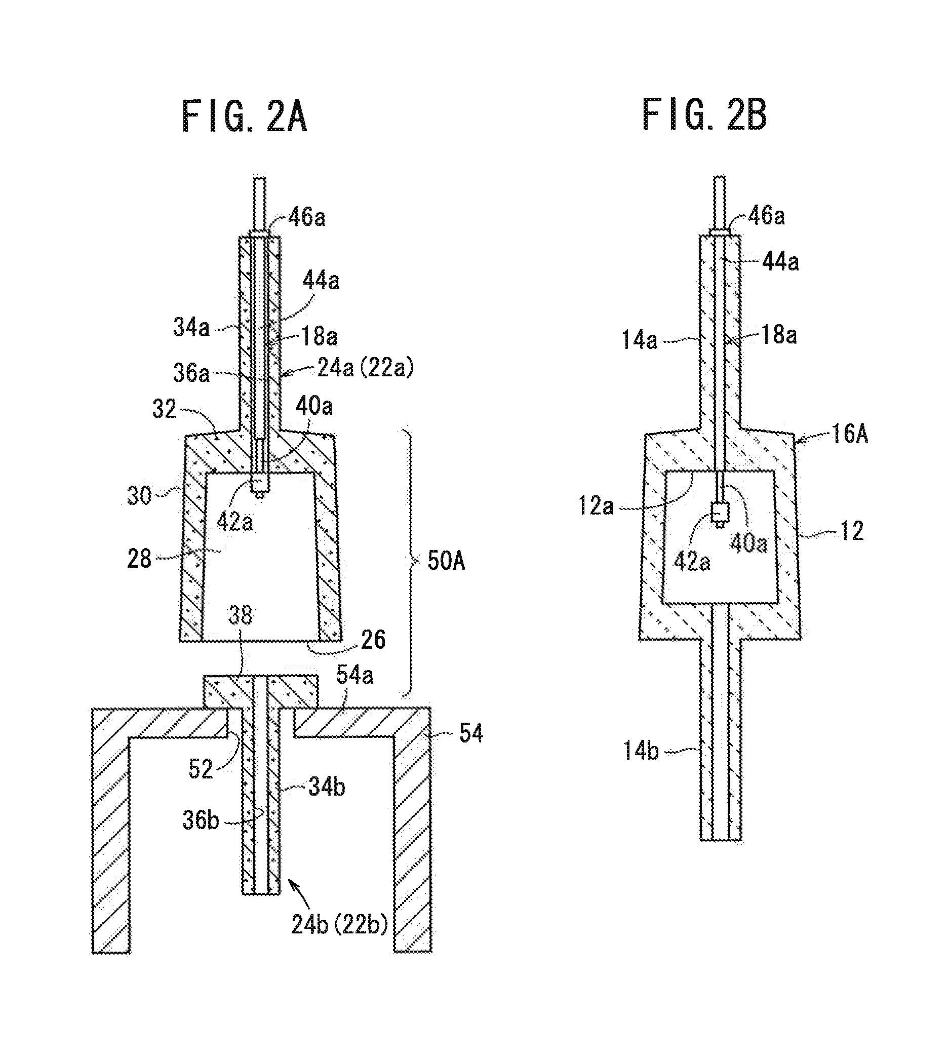
[0107]Ten arc tubes (first arc tube 10A) shown in FIG. 1 were fabricated by the first manufacturing method shown in FIG. 3. The first capillary 14a of the first ceramic tube 16A had an inside diameter of 0.5 mm and the second capillary 14b thereof had an inside diameter of 0.8 mm.

[0108]A forming slurry for fabricating the first ceramic compact 22a and the second ceramic compact 22b (see FIGS. 4A and 4B) was prepared as follows: 100 parts by weight of an alumina powder and 0.025 parts by weight of magnesia as a raw powder, 30 parts by weight of polybasic acid ester as a dispersion medium, 4 parts by weight of an MDI resin as a gellant, 2 parts by weight of a dispersant, and 0.2 parts by weight of triethylamine as a catalyst were mixed into a forming slurry.

[0109]The forming slurry was poured into a first casting mold and a second casting mold, both made of aluminum alloy, at the room temperature, and was left to stand at the room temperature for 1 hour. After the f...

##ventive example 2

INVENTIVE EXAMPLE 2

[0112]Ten sintered bodies (second ceramic tubes 16B) shown in FIG. 5 were fabricated by the second manufacturing method shown in FIG. 7. The inside diameter of the first capillary 14a was smaller than the inside diameter of the second capillary 14b.

[0113]Ten first ceramic compacts 22a and ten second ceramic compacts 22b (see FIGS. 4A and 4B) were fabricated in the same manner as with Inventive Example 1.

[0114]Thereafter, each of the first ceramic compacts 22a was pre-sintered at 1200° C. in the atmosphere to produce a first ceramic pre-sintered compact 24a, and each of the second ceramic compacts 22b was pre-sintered at 1000° C. in the atmosphere to produce a second ceramic pre-sintered compact 24b. Thereafter, using the jig 54 shown in FIG. 6A, the first ceramic pre-sintered compact 24a, the first electrode 18a, and the second ceramic pre-sintered compact 24b were successively assembled into a second assembled body 50B, which was then sintered at 1800° C. in an ...


PUM

PropertyMeasurementUnit
Diameteraaaaaaaaaa
Diameteraaaaaaaaaa
Diameteraaaaaaaaaa

Abstract

An arc tube includes a light emitting body for light therein and a ceramic tube having a first capillary and a second capillary integral with respective opposite sides of the light emitting body. A first electrode is inserted and sealed in the first capillary, and a second electrode is inserted and sealed in the second capillary. The first electrode is sealed in the first capillary by shrink fitting.

Description

CROSS-REFERENCE TO RELATED APPLICATION[0001]This application is based upon and claims the benefit of priority from Japanese Patent Application No. 2010-266658 filed on Nov. 30, 2010, of which the contents are incorporated herein by reference.BACKGROUND OF THE INVENTION[0002]1. Field of the Invention[0003]The present invention relates to an arc tube including a high-intensity discharge lamp such as a high-pressure sodium vapor lamp, a metal halide lamp, or the like, and a method of manufacturing such an arc tube, and more particularly to an arc tube having a ceramic tube which has a light emitting body for emitting light therein and a first capillary and a second capillary integral with respective opposite sides of the light emitting body, with a first electrode inserted and sealed in the first capillary and a second electrode inserted and sealed in the second capillary, and a method of manufacturing such an arc tube.[0004]2. Description of the Related Art[0005]Ceramic metal halide l...

Claims


Application Information

Patent Timeline
IPC IPC(8): H01J61/36H01J61/06H01R43/00
CPCH01J9/266H01J9/32Y10T29/49117H01J61/366H01J9/323
Inventor MIYAZAWA, SUGIOWATANABE, KEIICHIROOHASHI, TSUNEAKI
Owner NGK INSULATORS LTD
Why Eureka
Try Eureka