Partially compound-filled power supply unit and manufacturing method

Inactive Publication Date: 2012-05-31
FRIWO GERAETEBAU GMBH
View PDF26 Cites 15 Cited by
  • Summary
  • Abstract
  • Description
  • Claims
  • Application Information

AI Technical Summary

Benefits of technology

[0008]It is, therefore, the object of the present invention to provide a power supply unit and an associated manufacturing method allowing, on the one hand, the observance of a protection class that is suited for the operation in a moist area such as a bathroom and, on the other hand, the clear reduction of manufacturing costs and the complexity.
[0018]According to an advantageous embodiment of the present invention the electrical connection of the at least one power plug contact and / or the output lead to the board is realized by plug contacts which, in the fully mounted state, are arranged in the casting compound and are thereby electrically insulated. These contacts can be formed, for instance, by spring contacts which provide for an optimum electrical contact-making by means of a sliding movement as they are pushed on. As the casting compound is not yet hard at the time of mounting the circuit carrier, and if the spring contacts are arranged inside the casting space, undesired casting compound layers can be removed from the power plug pins and / or from the output leads in the required contact area by pushing on the spring contacts. Thus, a reliable contact-making is allowed. On the other hand, the power plug contacts or output leads and the associated spring contacts are mechanically fixed to each other on the circuit carrier by the casting compound in the fully mounted state, so that even strong tensile movements and vibrations are unable to influence the electrical contact-making.

Problems solved by technology

However, the ultrasonic welding alternative is not as process-reliable as the complete filling because the tightness depends on the quality of the welding seam and can be subject to certain unacceptable fluctuations.
Filling the plug-in power supply unit completely, on the other hand, has the disadvantage that the weight and the material expenditure are relatively high and, moreover, that the detection of causes of failure is rendered more difficult due to the fact that all of the components are inseparably enclosed by the casting resin.

Method used


Image

  • Partially compound-filled power supply unit and manufacturing method
  • Partially compound-filled power supply unit and manufacturing method
  • Partially compound-filled power supply unit and manufacturing method

Examples


first embodiment

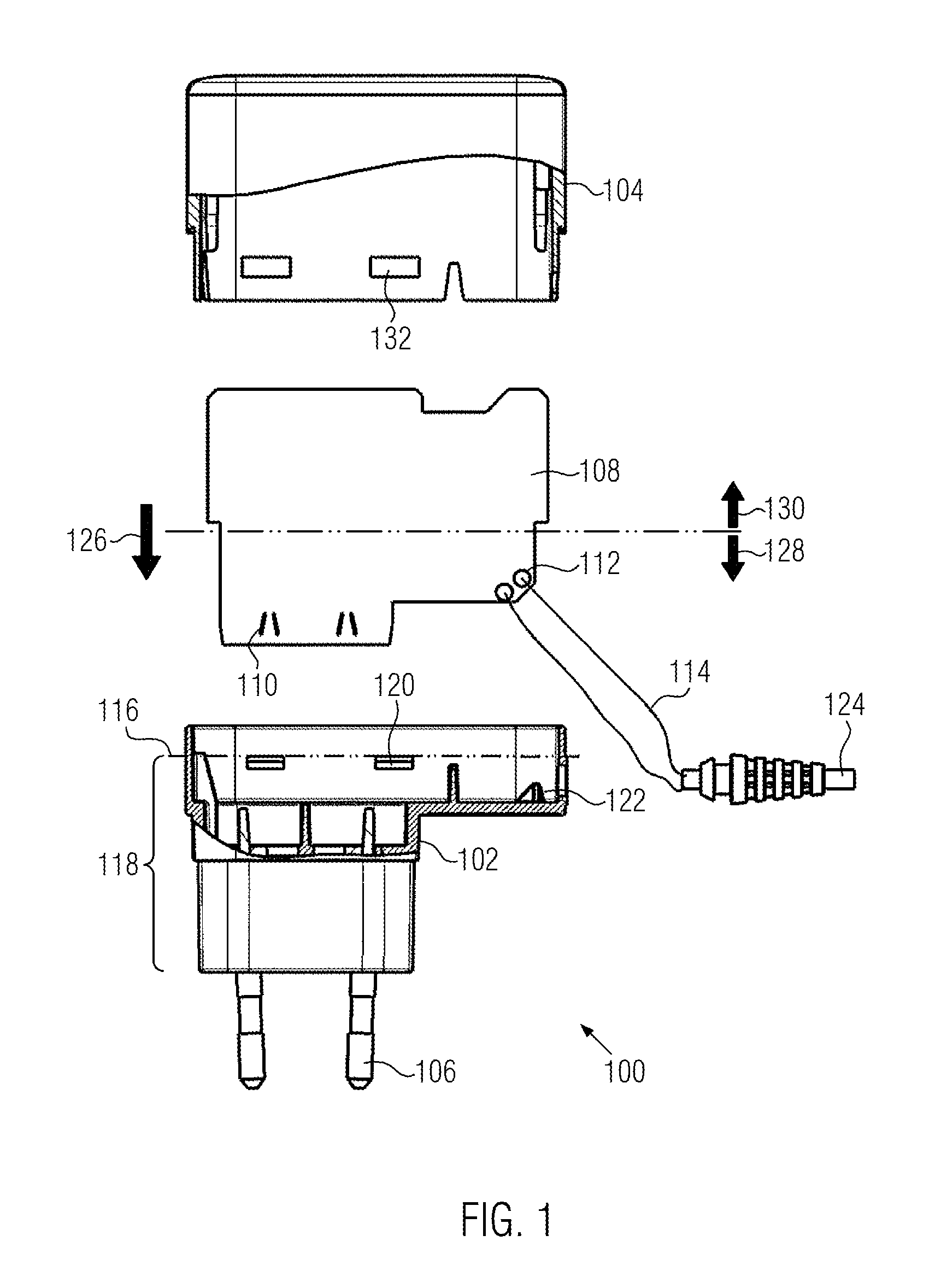
[0036] the leads for the power plug contacts 106, the snap-in noses 120 to be engaged with the lid element 104 as well as a holder and an aperture 122 for a strain relief 124 of the output lead 114 are located inside the casting space.

[0037]The printed circuit board 108, which is inserted into the casting space 118 in a direction 126 that runs substantially parallel to the plug-in direction of the power plug contacts 106 into a power socket, is divided into two regions: a first region 128 to be encapsulated, which is immersed in the casting compound and is arranged inside the casting space 118 of the casing base element 102 in the fully mounted state, and a second region 130 on which at least one electronic component is arranged and which remains without encapsulation.

[0038]According to the invention the connection between the output leads 114 and the second contacts 112 on the secondary side is established, for instance, by a soldered joint before the printed circuit board is mount...
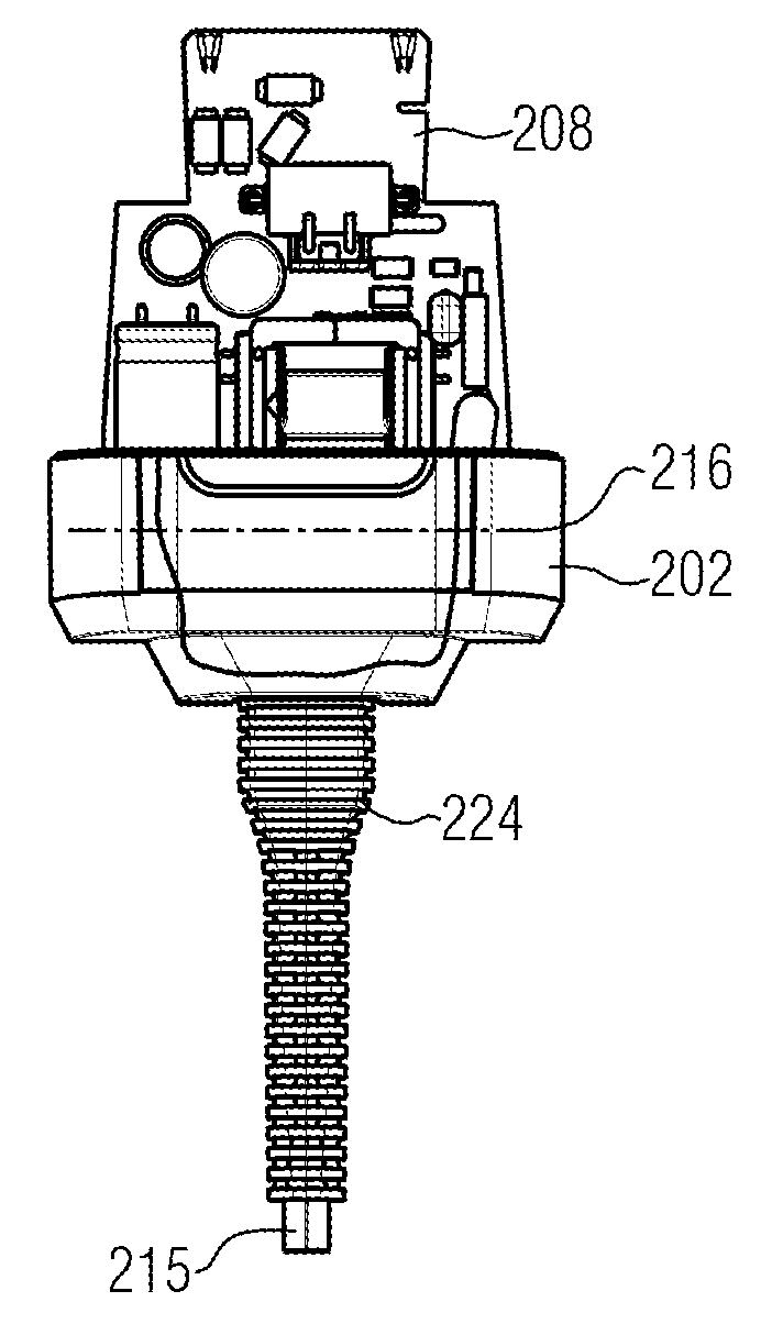
second embodiment

[0057]The final mounting step includes sliding on the lid element 204, which likewise has to be accomplished before the casting compound hardens in order to achieve a reliable sealing and a mechanically very stable connection between the casing base element 202 and the lid element 204. Apart from snap-in connections corresponding to the embodiment of FIGS. 1 to 7, anchoring apertures 233 may be arranged on the lid element of the second embodiment, into which the still liquid casting compound penetrates and, thus, forms mechanically stable anchors between the casing base element 202 and the lid element 204 after the hardening.

[0058]Moreover, as the lid element 204 is slid on, the electric contact between the spring contacts 210 and the power plug pins 206 is closed. The necessary contact protection and dielectric strength on this side of the plug-in power supply unit are guaranteed by the fact that the power plug pins are integrated in the lid element by encapsulation.

[0059]The gripp...


PUM

PropertyMeasurementUnit
Timeaaaaaaaaaa
Areaaaaaaaaaaa

Abstract

A power supply unit is provided for supplying low voltage power. The supply unit includes at least one power plug contact connectable to a supply voltage; at least one output lead for outputting the low voltage; and a voltage transformer unit having at least one electronic component for transforming the supply voltage to the low voltage. The power supply unit includes a casing made of a casing base element and a lid element, such that the power plug contact is held in the casing base element or in the lid element in such a way that it can be plugged into a power socket. The voltage transformer unit is mounted on a circuit carrier which is arranged in the casing base element in such a way that a defined first region of the circuit carrier is received in a casting space filled with an electrically insulating casting compound.

Description

BACKGROUND OF THE INVENTION[0001]The present invention relates to a power supply unit for supplying a consumer with a low voltage, and specifically to a so-called plug-in power supply unit in which power plug pins are arranged directly in the device so as to hold the power supply unit in the power socket during use.[0002]The present invention further relates to a manufacturing method for such a power supply unit.SUMMARY OF THE INVENTION[0003]Power supply units supplying a consumer with a low voltage by transforming the supply voltage into the necessary low voltage with the aid of a voltage transformer are nowadays widely spread. It is necessary for certain applications, e.g. for charging a shaver or an epilator, that the power supply unit can be safely operated in the moist atmosphere of a bathroom. Here, the protection class IPX4, or even IPX7 has to be observed.[0004]As is generally known this so-called IP code (Ingress Protection or International Protection) relates to the protec...

Claims


Application Information

Patent Timeline
IPC IPC(8): H02B1/32H05K3/00
CPCH01R13/5216H01R13/6658Y10T29/49124H01R43/005H01R13/6675H01R24/28F16H57/025H01R13/582H01R13/6633H01R2103/00
Inventor GAUSEPOHL, HEINZ-JURGENYILMAZ, TANER
Owner FRIWO GERAETEBAU GMBH
Why Eureka
Try Eureka