Power converting apparatus, grid interconnetion apparatus and grid interconnection system

a technology of power converting apparatus and grid interconnection, which is applied in the direction of process and machine control, secondary cell details, instruments, etc., can solve the problems of affecting conversion efficiency, increasing converter circuit, and dc-ac converter circuit output current distortion near the peak value, so as to reduce the distortion of output current waveform, reduce the increase of switching loss, and reduce the effect of high reliability

Inactive Publication Date: 2012-05-31
SANYO ELECTRIC CO LTD
View PDF3 Cites 21 Cited by
  • Summary
  • Abstract
  • Description
  • Claims
  • Application Information

AI Technical Summary

Benefits of technology

[0026]According to the feature, it is possible to configure the grid interconnection system using a power converting apparatus with reduced increase in switching loss an

Problems solved by technology

In such a power converting apparatus, there is a problem that, if input voltage (intermediate voltage) to the DC-AC converter circuit is insufficient with respect to a peak value of voltage that the DC-AC converter circuit should output, an output current of the DC-AC converter circuit is distorted near the peak value.
On the other hand, if the intermediate voltage is too

Method used


Image

  • Power converting apparatus, grid interconnetion apparatus and grid interconnection system
  • Power converting apparatus, grid interconnetion apparatus and grid interconnection system
  • Power converting apparatus, grid interconnetion apparatus and grid interconnection system

Examples


modification 1

(6) Modification 1

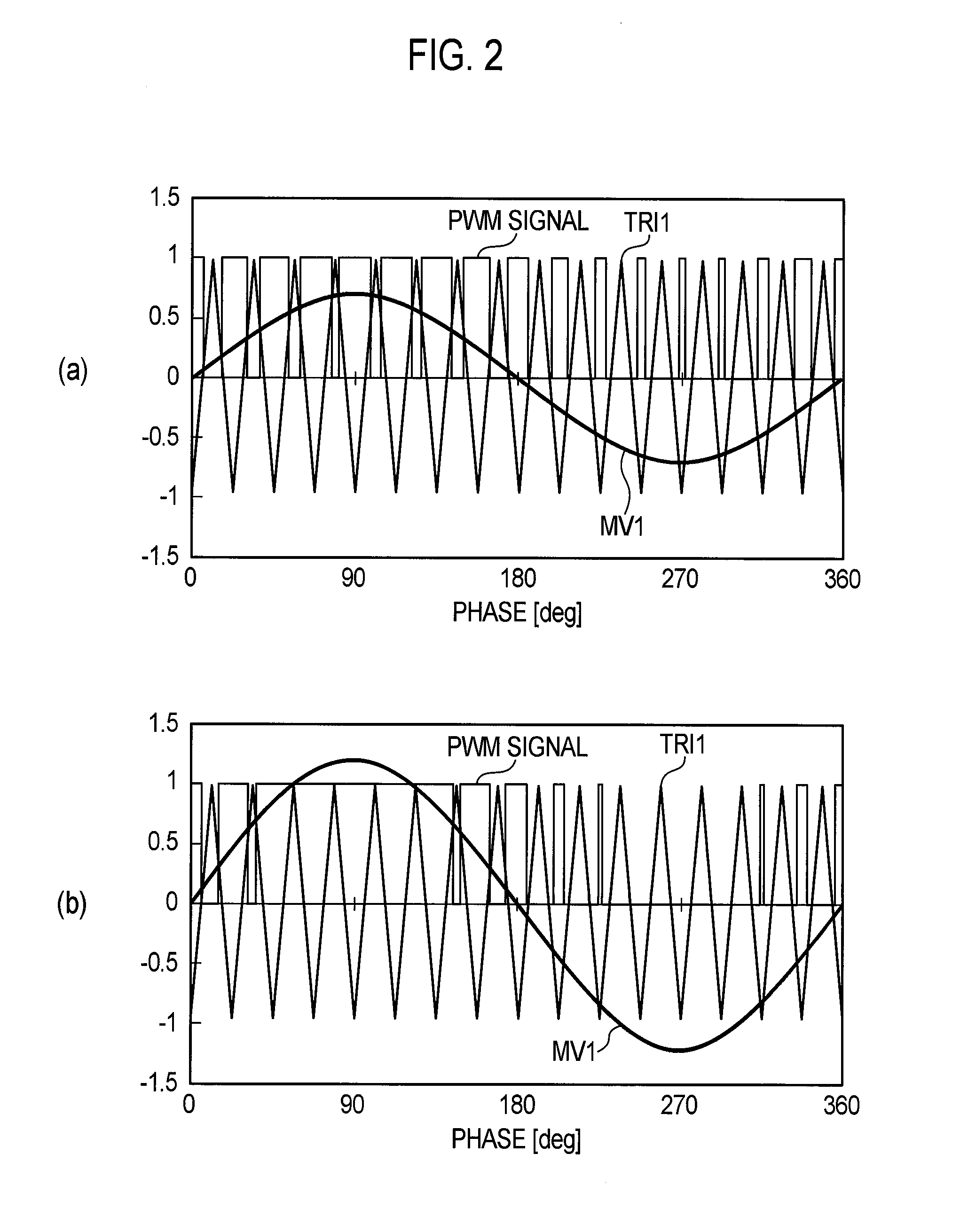
[0080]Next, Modification 1 of the process in the intermediate voltage target value setting unit 123 will be described. In Modification 1, the intermediate voltage target value setting unit 123 significantly increases the intermediate voltage target value SV2 in accordance with the increase of the peak value of the operating signal MV1 exceeding a range wider than the range of ±1 corresponding to the modulation factor of 0 to 100% (the range of ±1.2 in Modification 1).

[0081]FIG. 5 is a flowchart illustrating a process for each control period in the intermediate voltage target value setting unit 123 according to Modification 1. The process of FIG. 5 may be performed in combination with the process for each control period according to the embodiment described above. However, the process of FIG. 5 is not limited to be performed in combination with the process for each control period according to the embodiment described above, but may replace the process for each contr...

modification 2

(7) Modification 2

[0085]In particular, a solar cell is exemplified as the DC power supply in the first embodiment. In contrast, a storage battery is exemplified as the DC power supply in Modification 2. The operating signal is controlled in accordance with the intermediate voltage target value in the first embodiment. In contrast, the operating signal is controlled in accordance with the target modulation factor without using the intermediate voltage target value in Modification 2.

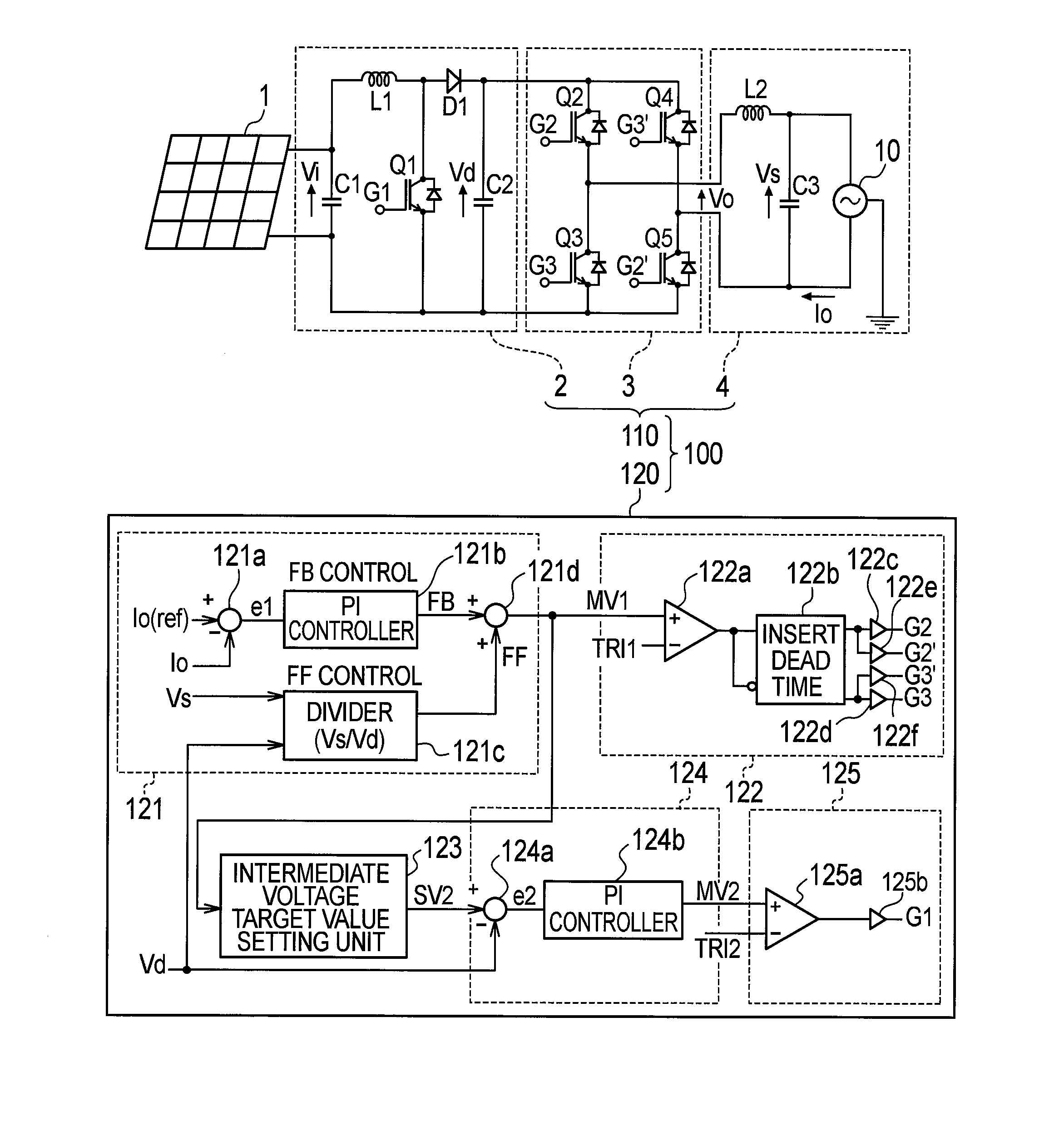
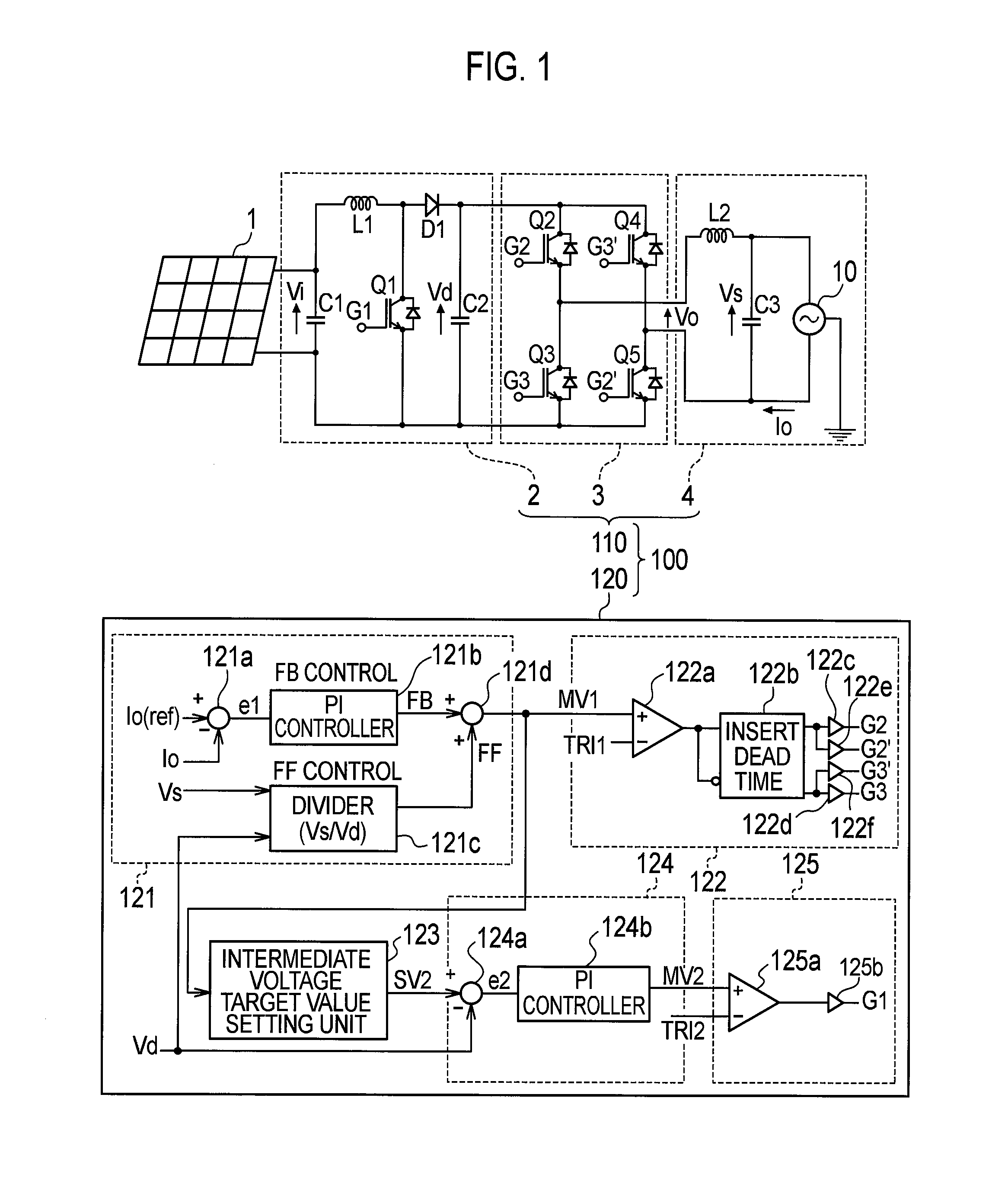
[0086]FIG. 6 is a configuration diagram of a grid interconnection system including a grid interconnection apparatus 100 according to Modification 2.

[0087]As illustrated in FIG. 6, the grid interconnection apparatus 100 is provided with a storage battery 1X in place of the solar cell 1, and a chopper circuit 2X in place of the step-up chopper circuit 2.

[0088]The storage battery 1X can be charged with electricity (charge). That is, the storage battery 1X has a function to be charged with electricity (charge)...


PUM


Abstract

A power converting apparatus comprises a DC-DC converter circuit that steps up or steps down an input voltage from a DC power supply, a DC-AC converter circuit that converts an intermediate voltage outputted by the DC-DC converter circuit to an alternate current, and a control circuit that controls the DC-DC converter circuit and the DC-AC converter circuit. The control circuit is provided with a circuit control unit that controls the DC-DC converter circuit so that the modulation factor, which is the amplitude ratio between a signal wave for manipulating the DC-AC converter circuit and the carrier wave therefor, will become a target modulation factor.

Description

CROSS REFERENCE[0001]This application is a Continuation of PCT Application No. PCT / JP2011 / 054403 filed on Feb. 25, 2011, and claims the priority of Japanese Patent Application No. 2010-042445, filed on Feb. 26, 2010, the content of both of which is incorporated herein by reference.TECHNICAL FIELD[0002]The present invention relates to a power converting apparatus, a grid interconnection apparatus and a grid interconnection system which steps up or down voltage from a DC power supply, such as a solar cell and a fuel cell, and then converts the voltage into AC voltage.BACKGROUND ART[0003]In the related art, this kind of power converting apparatus is provided with a DC-DC converter circuit which steps up or down voltage from a DC power supply, a DC-AC converter circuit (inverter) which converts output voltage (hereinafter, referred to as intermediate voltage) of the DC-DC converter circuit into AC, and a control unit which controls the DC-DC converter circuit and the DC-AC converter cir...

Claims


Application Information

Patent Timeline
IPC IPC(8): H02M7/537
CPCH01M10/02H01M2250/00Y02E10/563H02M7/53871H02M2001/007H02J3/383H02J2300/24H02J3/381Y02E10/56Y02E60/50Y02E60/10H02M1/007H02J3/40
Inventor YONEDA, FUMIIKI
Owner SANYO ELECTRIC CO LTD
Why Eureka
Try Eureka