
Inverter device adopting multi-winding transformer and multi-H-bridge structure and voltage output method thereof

A multi-winding transformer and voltage output technology, applied in the direction of irreversible DC power input conversion to AC power output, output power conversion device, AC power input conversion to DC power output, etc., can solve the problems of difficulty and cost increase , to achieve the effect of improving conversion efficiency and low power switching times

Inactive Publication Date: 2012-12-12
SHANDONG AITE MECHANICAL & ELECTRICAL TECH
View PDF3 Cites 4 Cited by
  • Summary
  • Abstract
  • Description
  • Claims
  • Application Information

AI Technical Summary

Problems solved by technology

Tsinghua University applied on March 17, 2011, and published on September 28, 2011. The Chinese invention patent with the publication number CN102201676, a method for controlling the voltage output of a hybrid H-bridge cascaded inverter, introduces a method suitable for The grid-connected controller of the cascaded H-bridge inverters with three DC bus voltage levels controls the corresponding switches of the three H-bridges through the voltage step modulation method or carrier pulse width modulation method according to the amplitude of the modulation wave. , so that the total output waveform of the H-bridge inverter is close to the ideal sinusoidal waveform; through its control method, the switching loss of the H-bridge inverter can be reduced when the output harmonics of the inverter system are small; but due to In terms of hardware structure, three H-bridges require three different DC buses, but for solar energy and other power generation and energy storage systems, there is only one DC bus, which will increase the difficulty and cost of implementation

Method used


Image

  • Inverter device adopting multi-winding transformer and multi-H-bridge structure and voltage output method thereof
  • Inverter device adopting multi-winding transformer and multi-H-bridge structure and voltage output method thereof
  • Inverter device adopting multi-winding transformer and multi-H-bridge structure and voltage output method thereof

Examples


Embodiment Construction

[0037] The present invention will be described in detail below in conjunction with the accompanying drawings and embodiments.

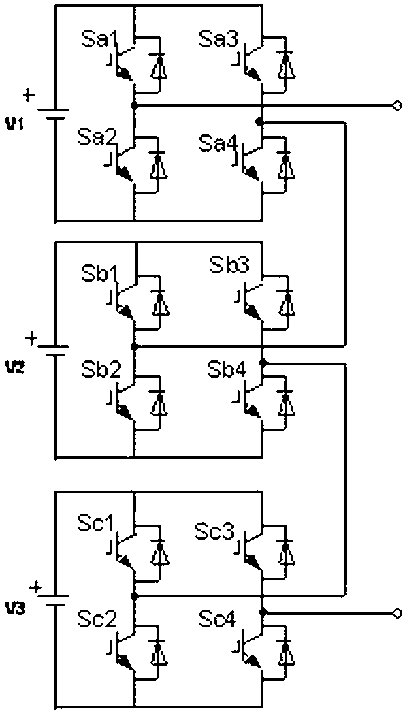
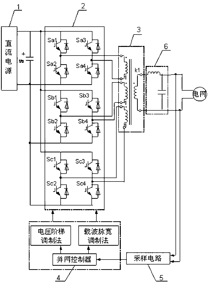
[0038] The present invention adopts an inverter structure consisting of three H-bridges 2 and a transformer 3 with three windings on the primary side and a single winding on the secondary side, wherein the input ends of the three H-bridges are connected in parallel to a voltage level of The three output ends are respectively connected to one primary side of the transformer, and the transformation ratio of the transformer is 1:1:1:k1; the control voltage output method of the inverter with this structure is that the sampling circuit 5 is a grid-connected controller Provide a sine wave with the same phase as the grid voltage signal, and the grid-connected controller 4 uses it as a modulated wave, and controls the switch states of the three H-bridges to output on the AC side through the voltage step modulation method or pulse width modulation method 、- ...


PUM


Abstract

The invention relates to an inverter device adopting a multi-winding transformer and a multi-H-bridge structure and a voltage output method of the inverter device. According to the method, firstly, a H-bridge inverter with three same direct-current voltage sources is provided and synchronized to a direct current bus at a voltage grade of Vo; the overall output voltage value of a secondary side of a transformer can meet the equation V=k1*(x+y+z)*Vo / 3; secondly, an ideal sine wave synchronized with a power grid is preset in a synchronization controller in the inverter system; thirdly, the ideal sine wave and a signal are modulated, corresponding switches of corresponding H bridges are respectively driven by a switch state of a modulated power switch according to the step condition in the signal, so that the overall output voltage waveform of the secondary side of the transformer approaches to the ideal sine wave after a wave filtering link. Under the condition of guaranteeing the output voltage performance, the switch loss can be largely reduced, and the energy transforming efficiency can be improved.

Description

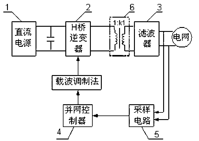
technical field [0001] The invention relates to a novel inverter device and a voltage output method thereof, in particular to an inverter device adopting a multi-winding transformer and a multi-H bridge structure and a voltage output method thereof. Background technique [0002] Currently, if figure 1 As shown, the inverter system includes DC power supply 1, H-bridge inverter 2 for DC (direct current, direct current)-AC (alternating current, alternating current) conversion, filter 3, grid-connected controller 4, and sampling circuit 5 and transformer 6. Generally, for a single-phase inverter system, an H-bridge inverter is used, which includes power switches Sa1 , Sa2 , Sa3 and Sa4 . Its working process is as follows: the sampling circuit samples the grid voltage, and generates a sine wave synchronized with the grid voltage in the grid-connected controller, and modulates the upper angular wave with the high-frequency triangular wave to obtain the four-way H-bridge inverter...

Claims


Application Information

Patent Timeline
IPC IPC(8): H02M7/42H02M7/5387H02M5/10
Inventor 路茂增马西庚张昊赵健徐峻涛
Owner SHANDONG AITE MECHANICAL & ELECTRICAL TECH
Learn More