Efficient thyristor-type power switches

a power switch and thyristor-type technology, applied in electronic switching, electrical equipment, pulse technique, etc., can solve the problems of many conventional circuit devices, especially those utilized in driver circuitry, found to be inoperative at cryogenic temperatures, and achieve the effect of reducing the loss of power supply, and increasing the switching speed of cryo-eto

Inactive Publication Date: 2008-04-01
MTECH LAB
View PDF9 Cites 5 Cited by
  • Summary
  • Abstract
  • Description
  • Claims
  • Application Information

AI Technical Summary

Benefits of technology

[0011]The hybrid switch methodology can also be applied to the ETO. In the HY-SETO device shown in FIG. 4, the switching function is accomplished using a cryo-cooled GTO, and the on-state conduction is handled by a second GTO that is warmer, e.g. approximately room temperature. The two GTOs are in similar ETO circuit branches that are connected in parallel. All emitter and gate MOSFET switches in FIG. 4 are cryo-cooled. High switching losses are a problem in all high-voltage thyristor-type circuits; here the increased switching speed of the Cryo-ETO at low temperatures alleviates these losses. In instances where the switching frequency is high, it may be beneficial to reverse the roles of the warm and cold GTOs, allowing the cryogenic GTO to conduct current while the warm GTO attends to the switching.

Problems solved by technology

Many conventional circuit devices, especially those utilized in the driver circuitry, have been found to be inoperative at cryogenic temperatures.

Method used


Image

  • Efficient thyristor-type power switches
  • Efficient thyristor-type power switches
  • Efficient thyristor-type power switches

Examples


Embodiment Construction

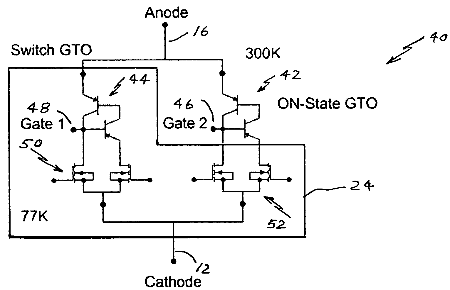
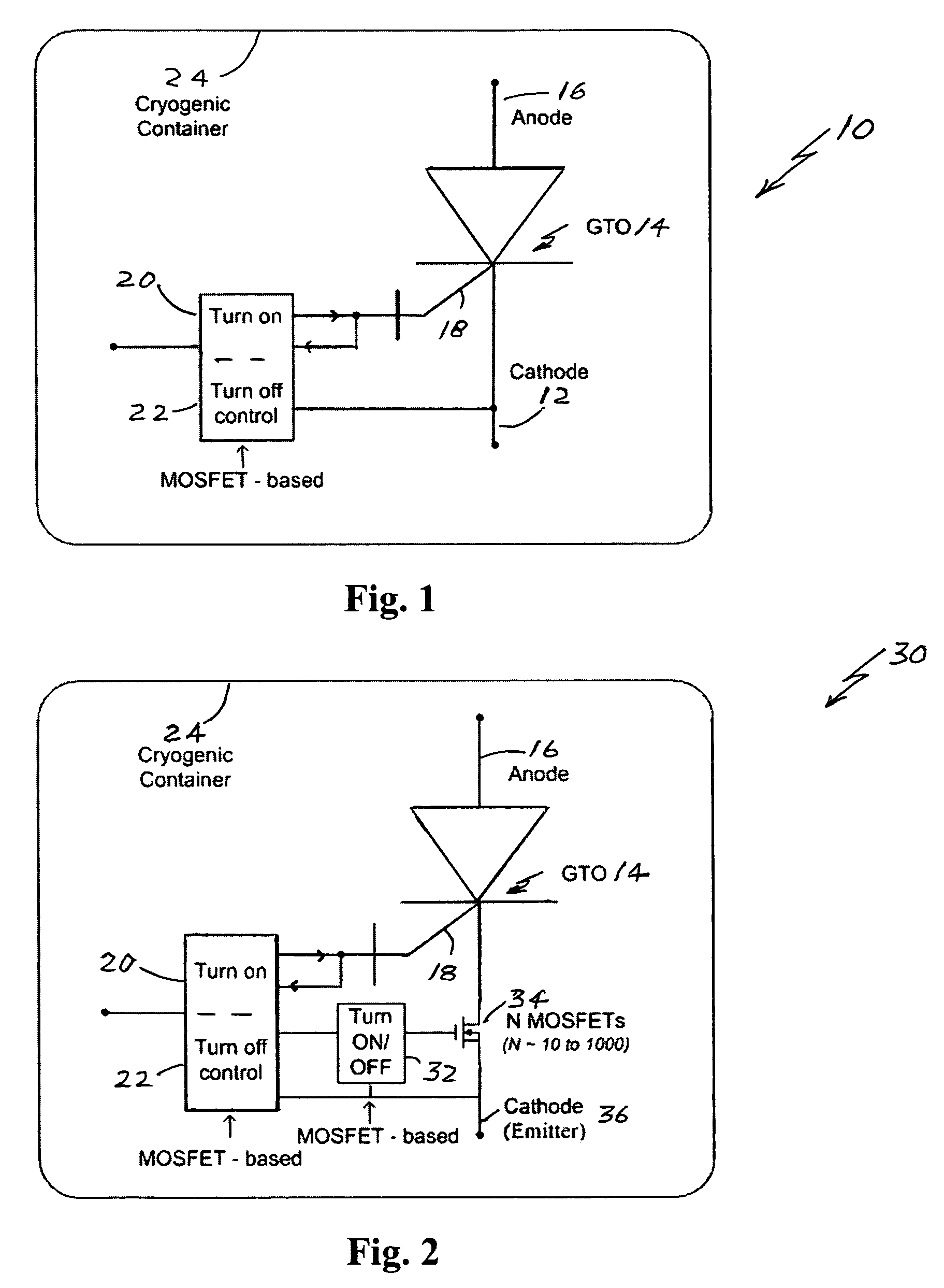
[0016]FIG. 1 is a functional block diagram of a Cryo-IGCT 10 and FIG. 2 is a Cryo-ETO 30 (also called a Super-ETO, or SETO). Each device is controlled by turn-on circuitry 20 and turn-off circuitry 22; both control circuits are best implemented using MOSFETs. The gate-cathode loop (18,12 and 18,36) inductance (not shown) is made as small as is physically possible. A gate turn-off thyristor (GTO) 14, made, e.g., of large circular silicon disks, is the main power switch. Features of the IGCT 10 and the ETO 30 are the “unity current gain turn-off” MOSFET driver circuits 20,22 (gate turn off current equals anode current).

[0017]For the ETO 30 (FIG. 2), several (N) paralleled low-voltage MOSFETs 34 (only one MOSFET 34 is illustrated to reduce drawing complexity) are series-connected to the cathode / emitter 36 of the GTO 14. The MOSFETs 34 are driven by the MOSFET-based drive circuit 32. (See U.S. application Ser. No. 10 / 857,118, ELAMP power systems, which is incorporated herein by referenc...


PUM


Abstract

The highest-power switches now available are based on thyristor-type devices: GTOs (Gate turn-off thyristors), MTOs (MOS controlled turn-off thyristors), IGCTs (Integrated gate commutated thyristors), and the new ETOs (Emitter turn-off thyristors). These devices handle kilovolts and kiloamperes for megawatt inverters/converters. Measurements by the inventors show that conduction losses of MOSFETs and switching losses of IGCTs are drastically decreased by cryo-cooling. IGCTs, ETOs, and MTOs, together with many small, low voltage MOSFETs for gate and emitter turn-off circuitry, are cryo-cooled to attain much higher switching speeds and a reduction in size, weight and cost of high-power (megawatt range) equipment.

Description

[0001]This patent claims the benefit of provisional patent application 60 / 579,085 filed Jun. 14, 2004.BACKGROUND OF THE INVENTION[0002]Combining GTOs (Gate Turn-Off thyristor) with MOSFETs yields new devices, including IGCTs (Integrated Gate Commutated Thyristors) and ETOs (Emitter Turn-Off thyristors). While these devices promise very high switching powers, they are relatively slow and exhibit high switching and conduction losses.[0003]FIGS. 1 and 2 show diagrams of an IGCT and an ETO. The measurements shown in the original data of FIG. 3 demonstrate how the critical turn-off times decrease with decreasing temperature of a IGCT thyristor switch [Ref. 2]. It was earlier known that GTOs provide similar improved performance at reduced temperatures. Turn-on and delay times (not shown) are also improved. Many additional measurements on IGCTs and MTOs (MOSFETs in gate turn-off circuitry) are presented in reference 2, which is an unpublished report prepared by the inventors. These FIG. 3 ...

Claims


Application Information

Patent Timeline
Patent Type & Authority Patents(United States)
IPC IPC(8): H03K17/72
CPCH03K17/06H03K17/732H03K17/92
Inventor MUELLER, OTWARDMUELLER, EDUARD K.HENNESSY, MICHAEL J.
Owner MTECH LAB
Why Eureka
Try Eureka