Redox flow battery

a technology of redox flow and battery, applied in the direction of indirect fuel cells, non-aqueous electrolyte cells, cell components, etc., can solve the problems of electrical power to be obtained, and achieve the effects of high charge/discharge efficiency, increased collision of solid particles, and high energy density

Inactive Publication Date: 2012-05-31
SHARP KK
View PDF2 Cites 126 Cited by
  • Summary
  • Abstract
  • Description
  • Claims
  • Application Information

AI Technical Summary

Benefits of technology

[0009]In a redox flow battery of the present invention, the negative electrode solution and/or the positive electrode solution are/is slurry type electrode solution and a current collector in the negative electrode cell and/or the positive electrode cell in the side containing the electrode solution are/is a porous current collector.
[0010]Use of the slurry type electrode solution makes it possible to realize an electric power storage system with high charge/discharge efficiency while keeping a high energy density.
[0011]Further, use of the porous current collector makes it possible to increase the collision of solid particles against the current collector even if the solid particles are used as an active material which causes a redox reaction in the slurry type electrode solution. As a result, the

Problems solved by technology

However, these energy sources are disadvantageous at a point that the electric power to be obtaine

Method used


Image

  • Redox flow battery
  • Redox flow battery
  • Redox flow battery

Examples


example 1

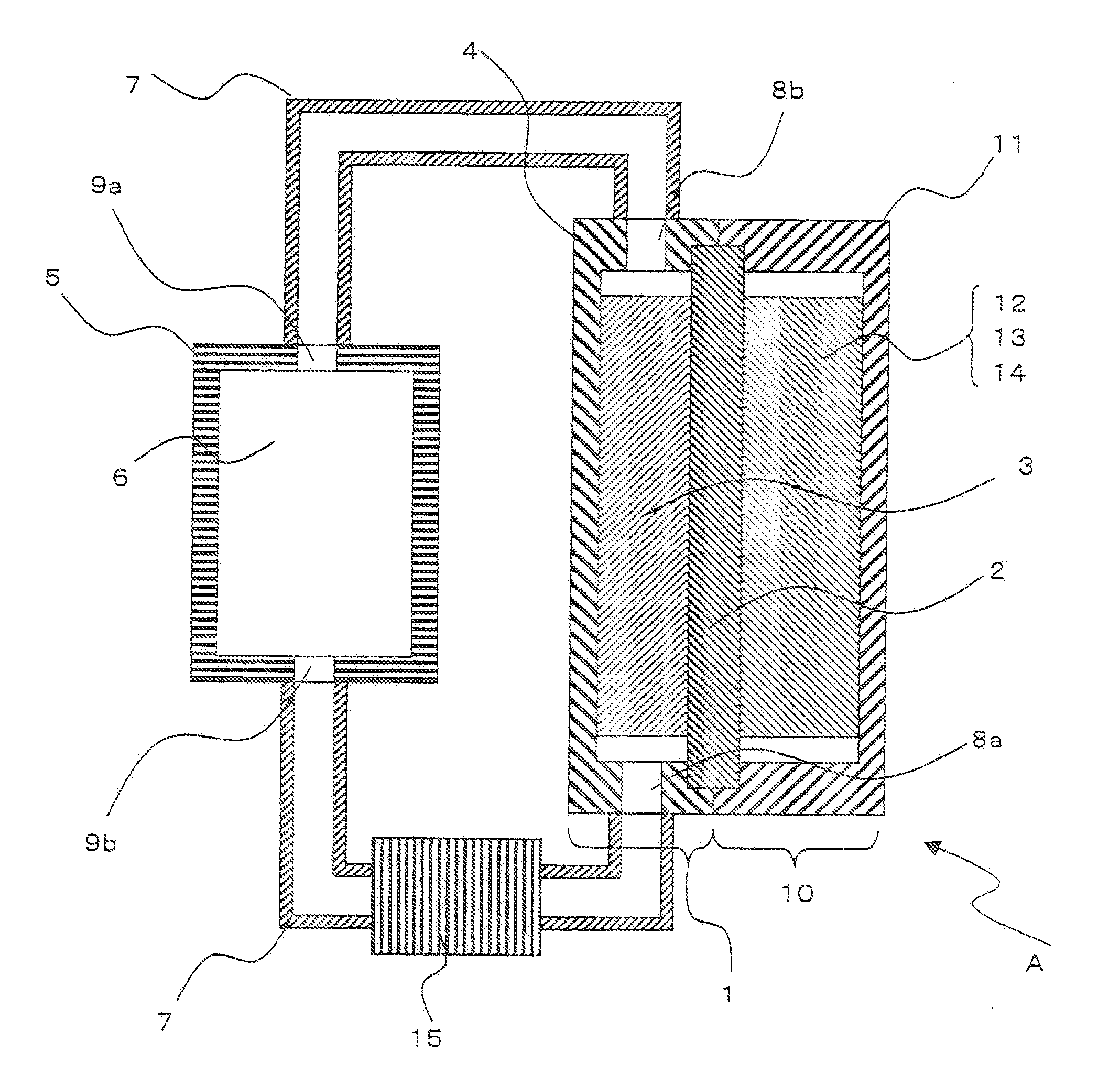
[0131]A redox flow battery shown in FIG. 1 was produced as follows.

[0132]At first, 100 ml of a mixed solvent of ethylene carbonate and dimethyl carbonate at a mixing ratio of 50:50 as a non-aqueous solvent, 5 g of a Li powder with an average particle diameter of 10 μm as solid negative electrode active material particles, and 10 g of lithium hexafluorophosphate as a supporting electrolyte were mixed in a chamber in inert Ar gas atmosphere. Next, the respective components in the mixture were dispersed by an ultrasonic probe to produce an aimed slurry type negative electrode solution.

[0133]On the other hand, 100 parts by weight of lithium cobaltate with an average particle diameter of 7 μm as a positive electrode active material, 5 parts by weight of acetylene black (Denka Black, manufactured by Denki Kagaku Kogyo K. K.) with an average particle diameter of 20 nm as a conductive auxiliary agent, and a PVdF solution (manufactured by Kureha Co., Ltd.) as a binder were adjusted and mixed...

example 2

[0141]Production and evaluation of a redox flow battery with energy density of 72 Wh / L were carried out in the same manner as those of Example 1, except that an aimed slurry type negative electrode solution was produced by mixing 100 ml of a mixed solvent of ethylene carbonate and dimethyl carbonate, 5 g of graphite (manufactured by Nippon Carbon Co., Ltd.) with an average particle diameter of 10 μm as solid negative electrode active material particles, and 10 g of lithium hexafluorophosphate as a supporting electrolyte were mixed in a chamber in inert Ar gas atmosphere and dispersing the respective components of the mixture by an ultrasonic probe.

[0142]Using a charge / discharge apparatus, the obtained redox flow battery was charged at a constant current of 0.1 A for 12 hours. Thereafter, when discharge was carried out at a constant current of 0.1 A for 10 hours, the open circuit voltage was 2.8 V. Even after 10 times of charge / discharge cycle, fluctuation of the liquid sending amoun...

example 3

[0143]Production and evaluation of a redox flow battery with energy density of 61 Wh / L were carried out in the same manner as those of Example 1, except that an aimed slurry type negative electrode solution was produced by mixing 100 ml of a mixed solvent of ethylene carbonate and dimethyl carbonate, 5 g of a lithium-tin alloy (Li:Sn=1:1 atom ratio) with an average particle diameter of 10 μm as solid negative electrode active material particles, and 10 g of lithium hexafluorophosphate as a supporting electrolyte were mixed in a chamber in inert Ar gas atmosphere and dispersing the respective components of the mixture by an ultrasonic probe.

[0144]Using a charge / discharge apparatus, the obtained redox flow battery was charged at a constant current of 0.1 A for 12 hours. Thereafter, when discharge was carried out at a constant current of 0.1 A for 10 hours, the open circuit voltage was 2.7 V. Even after 10 times of charge / discharge cycle, fluctuation of the liquid sending amount due to...


PUM


Abstract

A redox flow battery comprising an electrode cell including a negative electrode cell, a positive electrode cell and a separator for separating them, in which at least one of the negative electrode cell and the positive electrode cell includes a slurry type electrode solution, a porous current collector and a casing; a tank for storing the slurry type electrode solution; and a pipe for circulating the slurry type electrode solution between the tank and the electrode cell.

Description

TECHNICAL FIELD[0001]The present invention relates to a redox flow battery. Further in detail, the present invention relates to a redox flow battery using a slurry type negative electrode solution and / or positive electrode solution.BACKGROUND ART[0002]Renewable clean energy such as photovoltaic power generation, wind power generation, hydroelectric power generation, etc. is highly expected to be main energy sources in place of fossil energy sources. However, these energy sources are disadvantageous at a point that the electric power to be obtained is considerably fluctuated depending on the environmental changes since utilizing natural energy. Therefore, at the time of supplying the electric power obtained by these energy sources to a presently existing electric power system including a thermal electric power generation or nuclear electric power generation, it is needed to once store electric power for stabilization and then supply the electric power.[0003]For such electric power st...

Claims


Application Information

Patent Timeline
IPC IPC(8): H01M4/38H01M4/48H01M2/00
CPCH01M8/188Y02E60/528H01M8/20Y02E60/50Y02P70/50
Inventor YOSHIE, TOMOHISANISHIMURA, NAOTOTSUKUDA, YOSHIHIROUTSUMI, HISAYUKIWATANABE, YUKIYOSHIDA, AKIHITOSATA, SHUNSUKETAKENAKA, SHINOBUKAGA, MASAKI
Owner SHARP KK
Why Eureka
Try Eureka