Multi-directional microfluidic devices comprising a pan-capture binding region and methods of using the same

a multi-directional microfluidic and binding region technology, applied in the field of multi-directional microfluidic devices comprising a pan-capture binding region, can solve the problems of inability to meet the performance needs of high-throughput sample analysis, impractical for clinical use, and conventional blotting techniques, as discussed above, to achieve the effect of facilitating electrostatic binding of analytes

Inactive Publication Date: 2012-05-31
RGT UNIV OF CALIFORNIA
View PDF12 Cites 17 Cited by
  • Summary
  • Abstract
  • Description
  • Claims
  • Application Information

AI Technical Summary

Benefits of technology

[0006]The binding medium may be configured to non-specifically bind to analytes in the sample through electrostatic interactions. For instance, the binding medium may be configured to have a negative charge. In some instances, the binding medium includes a negatively charged gel. In certain embodiments, the binding medium includes a negatively charged pan-capture binding member stably associated with a support. In some cases, the fluid sample includes a detergent. The detergent may be configured to provide analytes in the sample with a positive charge. Embodiments that include a negatively charged gel and a detergent that gives analytes in the sample a positive charge may facilitate electrostatic binding of the analytes to the binding medium. In certain instances, the detergent is cetyltrimethylammonium bromide.

Problems solved by technology

Conventional blotting techniques, as discussed above, may fall short of performance needs for applications that demand either high-throughput sample analysis or operation in resource poor settings.
Blotting techniques may require labor-intensive, time consuming, multi-step procedures carried out by a trained technician, and thus may be impractical for use in a clinical setting.

Method used


Image

  • Multi-directional microfluidic devices comprising a pan-capture binding region and methods of using the same
  • Multi-directional microfluidic devices comprising a pan-capture binding region and methods of using the same
  • Multi-directional microfluidic devices comprising a pan-capture binding region and methods of using the same

Examples


example 1

Design of Microfluidic Device

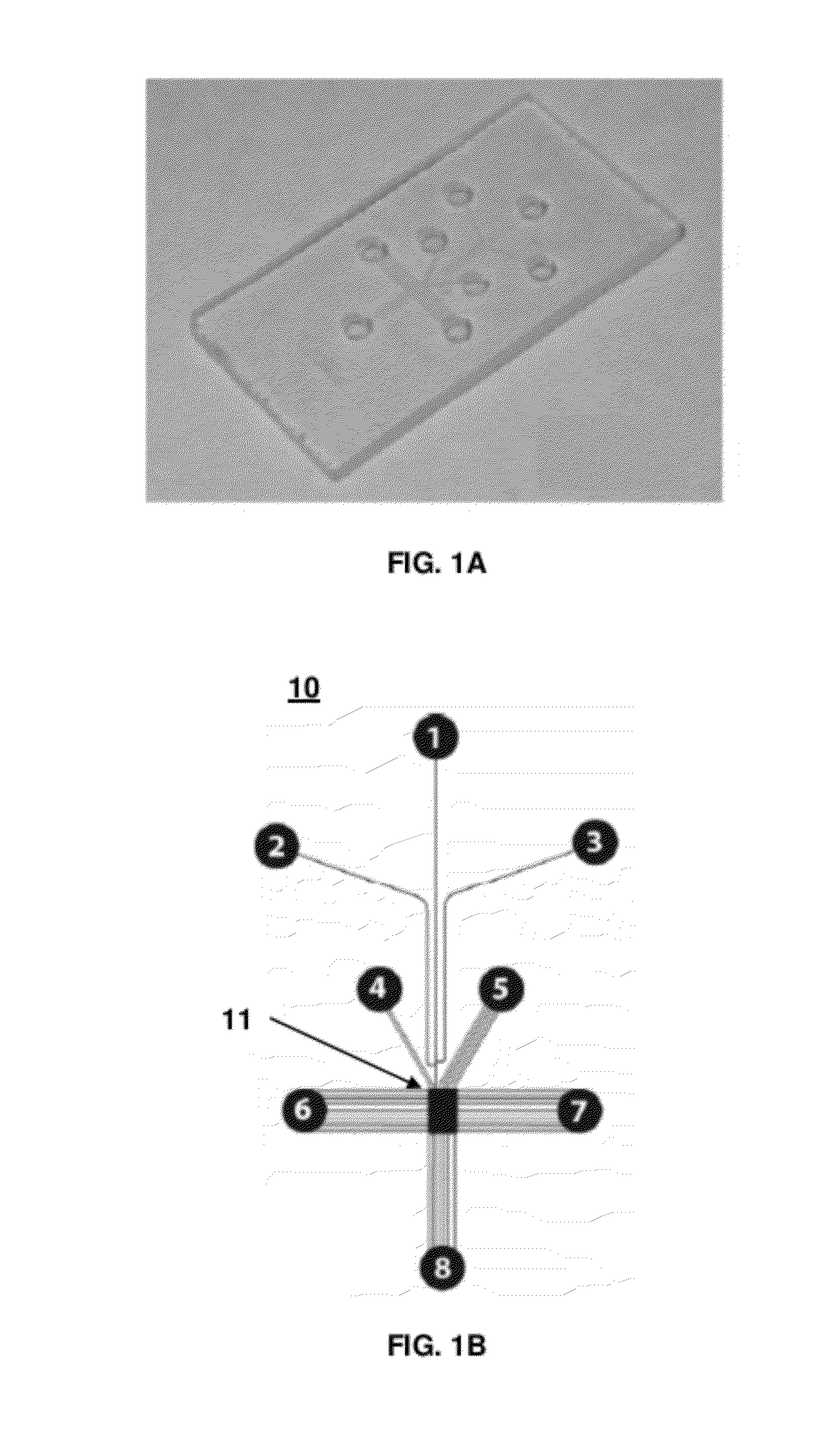
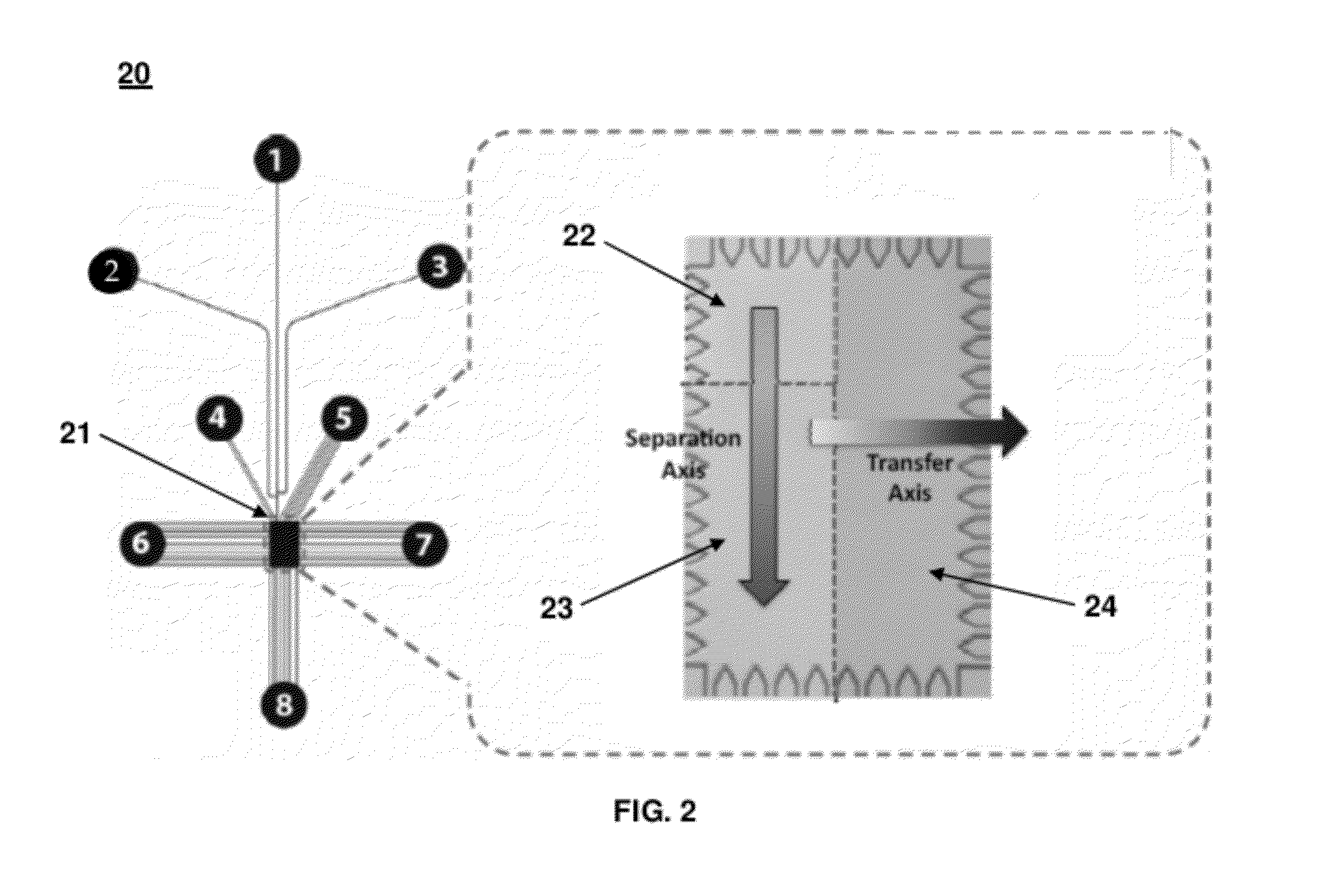
[0110]A glass microfluidic chip (10 mm×15 mm) (FIG. 1A) was designed using Autocad software (Autodesk, San Rafael; Calif.). A rectangular microfluidic chamber (1 mm×1.5 mm×0.02 mm) was designed to accommodate three functional gel regions for different Western blotting steps. FIG. 2 shows a schematic of the microfluidic chamber that included the loading gel for sample loading, the separation gel for protein sizing, and the blotting gel for transfer and target probing. The chamber was connected with several microfluidic channels, such as the injection channels and control channels. The width of each injection channel was 25 μm, and the width of each control channel was 10 μm. The injection channel was branched into three channels (see channels 1, 2, and 3 in FIG. 2) that formed a double-T junction, where a narrow sample plug was formed by applying a pinch current. Control channels (see channels 4, 5, 6, 7, and 8 in FIG. 2) were also linked to the chamber. ...

example 2

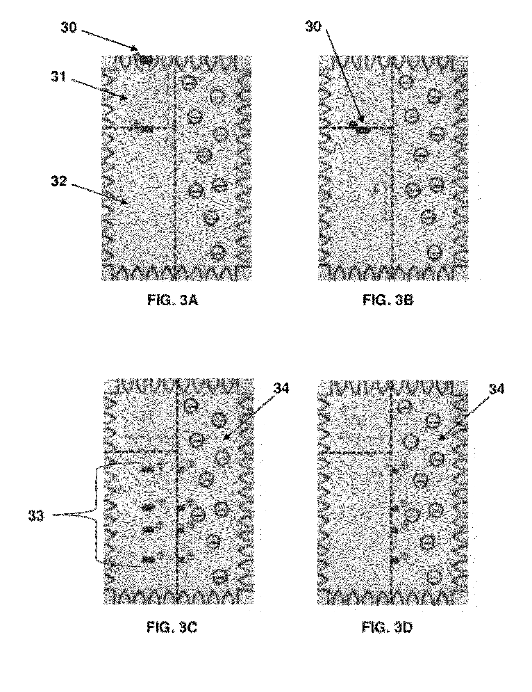
[0122]Experiments were performed using the same experimental protocol as Example 1 to determine the transfer efficiency and reproducibility of the assay. The binding member (e.g., capture protein) used in the fabrication of the binding medium of the microfluidic device was 150 kDa IgG (anti-C-reactive protein). A sample containing protein G (20 kDa), OVA (45 kDa), BSA (68 kDa), and α-actinin (95 kDa) was separated in the separation medium and transferred to the binding medium. The separation step was completed in 21 sec after loading the sample (FIG. 10A). FIG. 10B shows a fluorescence image during the transfer of the separated sample 35 s after sample loading. Transfer of the separated sample from the separation medium 1010 to the binding medium 1020 was completed in 42 sec (e.g., 63 sec after sample loading) (FIG. 10C). Proteins were retained by the binding medium 1020 even after washing the bound proteins with buffer, as shown in the fluorescence image in FIG. 10D, taken 139 s af...

example 3

[0123]Experiments were performed using the same experimental protocol as Example 1 to determine the transfer efficiency and reproducibility of the assay. The binding member (e.g., capture protein) used in the fabrication of the binding medium of the microfluidic device was 465 kDa β-galactosidase (pl=4.61). A sample containing protein G (20 kDa), OVA (45 kDa), BSA (68 kDa), and α-actinin (95 kDa) was separated in the separation medium and transferred to the binding medium. The separation step was completed in 18 sec after loading the sample (FIG. 11A). FIG. 11B shows a fluorescence image during the transfer of the separated sample 21 s after sample loading. Transfer of the separated sample from the separation medium 1110 to the binding medium 1120 was completed in 20 sec (e.g., 38 sec after sample loading) (FIG. 11C). Proteins were retained by the binding medium 1120 even after washing the bound proteins with buffer, as shown in the fluorescence image in FIG. 11D, taken 53 s after s...


PUM

PropertyMeasurementUnit
molecular massaaaaaaaaaa

Abstract

Microfluidic devices and methods for using the same are provided. Aspects of the invention include microfluidic devices that include a separation medium and a pan-capture binding medium. The microfluidic devices are configured to subject a sample to two or more directionally distinct electric fields. Also provided are methods of using the devices as well as systems and kits that include the devices. The devices, systems and methods find use in a variety of different applications, including diagnostic and validation assays.

Description

CROSS-REFERENCE TO RELATED APPLICATIONS[0001]Pursuant to 35 U.S.C. §119(e), this application claims priority to U.S. Provisional Patent Application No. 61 / 416,693 filed on Nov. 23, 2010, the disclosure of which is herein incorporated by reference in its entirety.INTRODUCTION[0002]A variety of analytical techniques may be used to detect specific analytes in a given sample. For example, Western blotting can be used to detect proteins in a sample by using gel electrophoresis to separate the proteins in the sample followed by probing with antibodies specific for the target protein. Southern blotting combines transfer of electrophoresis-separated DNA fragments to a filter membrane and subsequent fragment detection by probe hybridization. Northern blotting involves the use of electrophoresis to separate RNA samples by size and detection with a hybridization probe complementary to part of or the entire target sequence. Eastern blotting can be used to detect protein post translational modif...

Claims


Application Information

Patent Timeline
Patent Type & Authority Applications(United States)
IPC IPC(8): G01N33/566G01N1/18G01N30/00
CPCG01N27/44791Y10T436/25375G01N2550/00B01L3/502707B01L3/502715B01L3/50273B01L3/502753B01L2200/0652B01L2300/0636B01L2300/0816B01L2300/0819B01L2300/0864B01L2300/0867B01L2400/0406B01L2400/0415B01L2400/0421B01L2400/0672G01N33/6803G01N33/54306G01N33/6842Y10T436/255
Inventor HERR, AMY E.KIM, DOHYUN
Owner RGT UNIV OF CALIFORNIA
Why Eureka
Try Eureka