
Stent Graft System

Inactive Publication Date: 2012-05-31
CHEN WEI HUI
View PDF4 Cites 11 Cited by
  • Summary
  • Abstract
  • Description
  • Claims
  • Application Information

AI Technical Summary

Benefits of technology

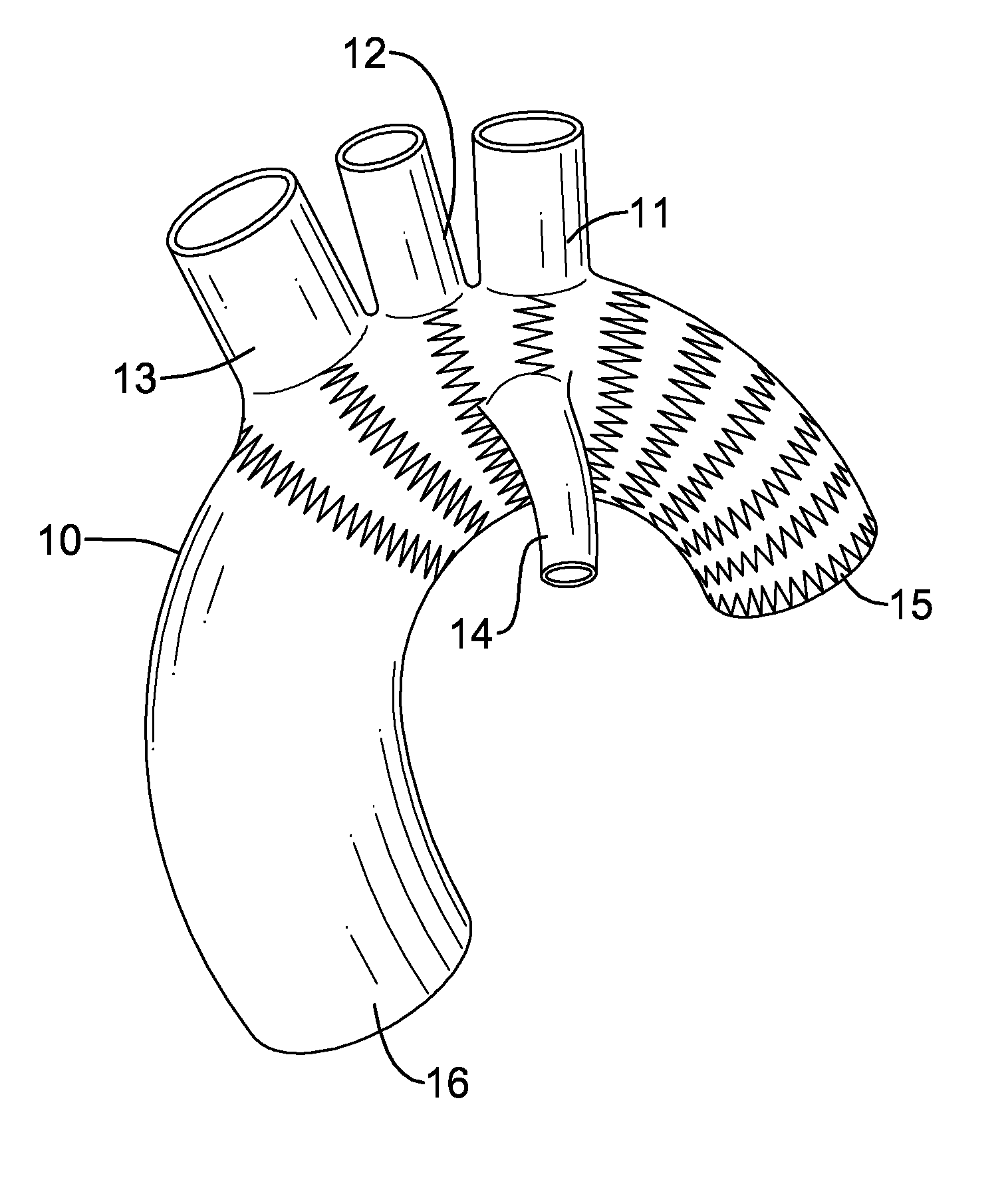
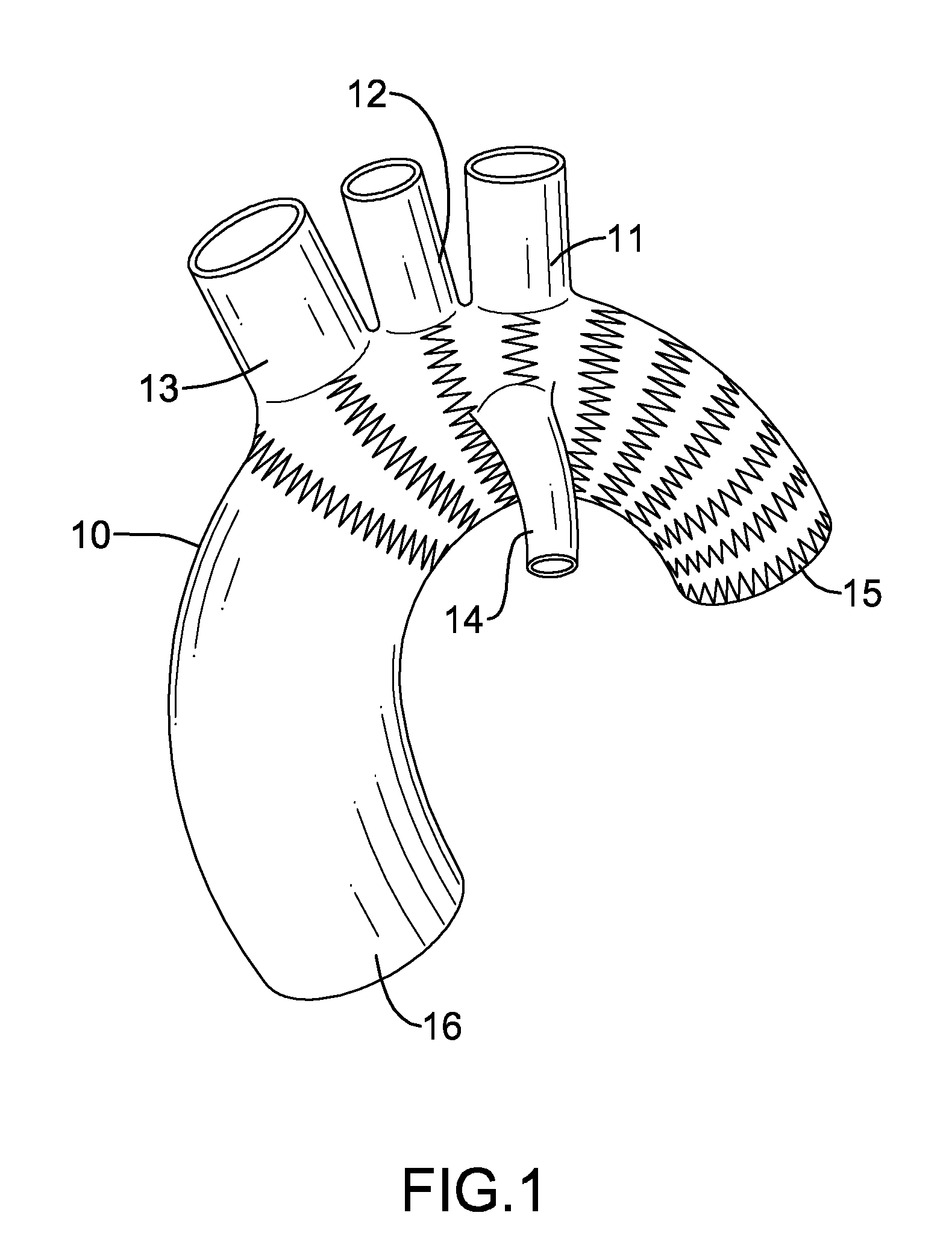
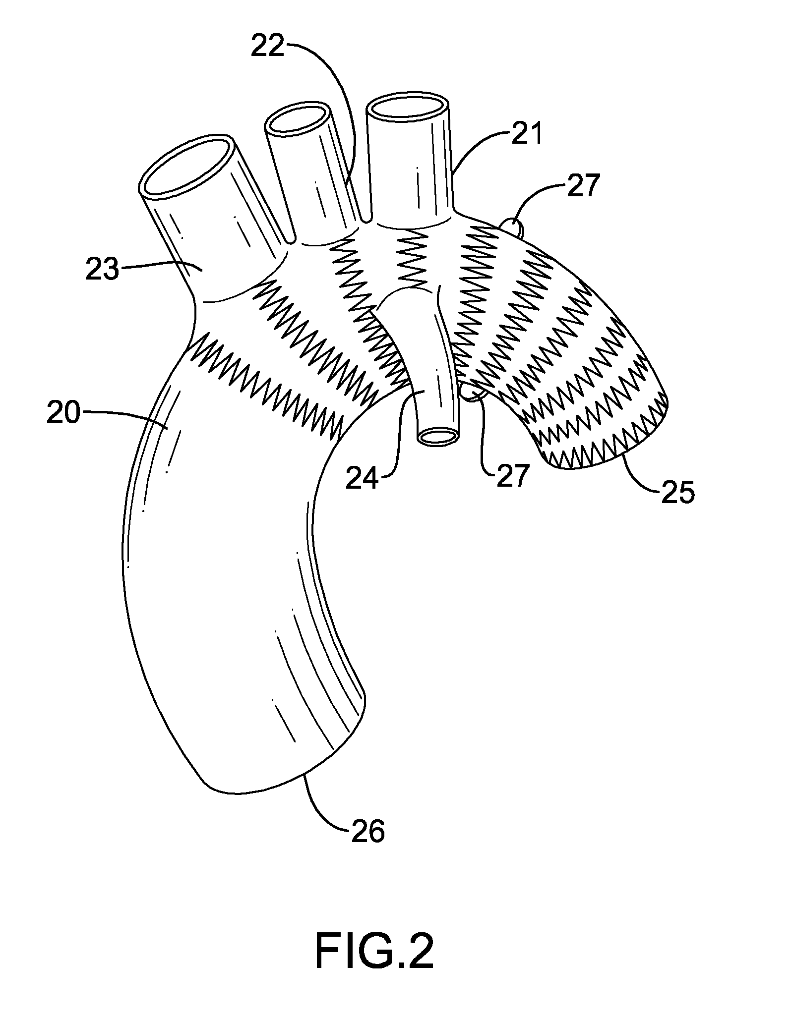
[0015]With the above-described structure, the present invention allows a surgeon to separately select a suitable trunk, a left subclavian tube, a left common carotid tube and a brachiocephalic tube in the aortic arch surgery, which takes far less time than selecting a complete stent graft that coincidentally fits the aortic arch as well as the arteries of the patient. Furthermore, the structure of the stent graft system allows a medical institute to prepare compatible branch tubes and trunks for a composite stent graft system instead of numerous stent grafts of various combinations of differently sized tubular bodies and branches, wherein the former requires significantly less warehousing cost than the latter.

Problems solved by technology

However, the tightening made possible by the expanding stents is observed to be insufficient to endure the pressure of the blood steam from ascending aorta and fails to sustain the trunk 91.
One apparent problem of the solution is its unacceptable expensiveness.
In a clinical aspect of the custom-made stent grafts a more significant problem arises: custom-made stent grafts usually fail to provide clinically realistic readiness, especially in an emergent surgery.
Said structural nature of conventional stent grafts also costs the surgeon considerable time for selecting a stent graft with specifically suitable tubular trunks 91, 92 and suitable branches 911-913, 921-923, prior to or during an emergent surgery, such as acute aortic dissection or ruptured aortic aneurysm, in which the customized branched stent graft cannot be available timely.

Method used


Image

  • Stent Graft System
  • Stent Graft System
  • Stent Graft System

Examples


first embodiment

[0043]With reference to FIG. 5, a branch tube 41 for use as a left subclavian tube, a left common carotid tube or a brachiocephalic tube of the stent graft system in accordance with the present invention is expandable, preferably self-expandable or balloon-expandable made from a clinically blood-impermeable material, preferably polyester or polytetrafluoroethylene, where expandable stents are mounted on inner or outer surfaces of the branch tube 41. The expandable stents may be made of meshes, springs or a combination thereof, and comprises a proximal end and a distal end. Preferably, the material of the stents may be Nitinol, stainless steel, Co—Cr alloy, or other clinically acceptable material. With reference to FIGS. 1-4, 14 and 15, the proximal end of the branch tube 41 is for mounting the left subclavian mount 11, 21, 31, the left common carotid mount 12, 22, 32 or the brachiocephalic mount 13, 23, 33. The distal end is for connecting to the left subclavian artery, the left com...

third embodiment

[0048]With reference to FIG. 8, a forth embodiment of a branch tube 44 similar to the aforementioned third embodiment comprises an outer surface and multiple rings 441. The rings 441, attached to the outer surface of the branch tube 44 in a similar manner as the tabs 431 to the branch tube 43 in FIG. 7, allow seaming materials to pass through them, so to provide convenience in surgery.

second embodiment

[0049]With further reference to FIGS. 1-4 and 6, a similar embodiment to the foregoing second embodiment of the branch tube 42 further comprises a reinforce ring formed on the outer surface around the proximal end of the branch tube 42. The reinforced ring is elastic and capable of being deformed and compressed when mounted in a mount 11-13, 21-23, 31-33 of a trunk 10, 20, 30. When the instant embodiment is deployed in the mount 11-13, 21-23, 31-33 and one of the three supra-aortic arteries, the ring is fully expanded and can be engaged on the margin of mount.

[0050]With further reference to FIGS. 1-4, 5 and 9, the present invention also provides a fifth embodiment of a branch tube 45 similar to the aforementioned embodiment of the branch tube 41, wherein no barbs as mentioned in the second embodiment of the branch tube 42, however equipped with the above-described reinforced ring 451 formed on the outer surface around the proximal end.

[0051]With reference to FIG. 10, a sixth embodim...


PUM


Abstract

The stent graft system in accordance with the present invention has a trunk, a left subclavian tube, a left common carotid tube and a brachiocephalic tube. The trunk is tubular and expandable and has a descending end, an ascending end, a left subclavian mount, a left common carotid mount and a brachiocephalic mount, for receiving the aforementioned branch tubes that are elastic and self-expandable for respectively connecting the left subclavian artery, the left common carotid artery and the brachiocephalic artery to the trunk. With the above-described structure, the present invention allows fast determination of a suitable trunk and branch tubes for a patient and allows a medical institute to prepare compatible branch tubes and trunks for a composite stent graft system instead of numerous stent grafts of various combinations of differently sized tubular bodies and branches, wherein the former requires significantly less warehousing cost than the latter.

Description

BACKGROUND OF THE INVENTION[0001]1. Field of the Invention[0002]The present invention relates to a stent graft system, especially to a composite branched stent graft system.[0003]2. Description of the Prior Art[0004]With reference to FIG. 18, a first conventional stent graft or prosthesis for open aortic arch surgery is used to support inner wall thereof as a treatment for aortic dissection or aortic arch aneurysm and comprises a tubular trunk 91, a left subclavian arterial branch 911, a left common carotid arterial branch 912 and a brachiocephalic arterial branch 913. The tubular trunk 91 is made of self-expandable elastic material with expandable stents and comprises two ends 914, 915 for connecting to portions of the aortic arch. The two ends 914, 915 of the tubular trunk 91, when mounted in the aortic arch, self-expand and thus attach themselves to the inner walls of the portions of aortic arch. The portion of the vicinity of the end 915 also comprises the expandable stents so a...

Claims


Application Information

Patent Timeline
IPC IPC(8): A61F2/82A61F2/06
CPCA61B17/11A61B2017/1107A61B2017/1132A61F2/064A61F2/07A61F2220/0033A61F2002/821A61F2220/0075A61F2250/006A61F2/89A61F2002/072A61F2002/061
Inventor CHEN, WEI-HUI
Owner CHEN WEI HUI
Learn More