Trace particle collection system

a trace particle and collection system technology, applied in the field of trace chemicals, can solve the problems of difficult to remove target particles by simple means, low momentum transfer methods, and difficult to remove target particles of explosives or narcotics from rigid surfaces, and achieve the effect of avoiding excessive emissions and high hardness

Active Publication Date: 2012-06-07
LEIDOS SECURITY DETECTION & AUTOMATION INC
View PDF9 Cites 26 Cited by
  • Summary
  • Abstract
  • Description
  • Claims
  • Application Information

AI Technical Summary

Benefits of technology

[0015]The frozen carbon dioxide aerosol particle material may be selected to provide no significant damage to the target surface. Aerosol particles with a high hardness, such as silica or alumina, are abrasive and may damage the target surface as a result of the high velocity impact. Carbon dioxide is an oxide and has no flashpoint, which may be noted as an important characteristic when working with finely divided materials.
[0016]The frozen carbon dioxide aerosol mixture may be non-toxic and harmless to humans and animals, as long as the aerosol is not directed into the eyes. The frozen carbon dioxide aerosol mixture may be pulsed to avoid excessive emissions into a confined space, since the carbon dioxide gas residue may displace the oxygen in air.
[0017]The frozen carbon dioxide aerosol particles may impact the target particles on the target surface and provide sufficient momentum transfer to dislodge the target particles from the target surface and become entrained in a puff of gas transporting the aerosol particles. The dislodged target particles and aerosol particles may then be collected by the particle transport component. The frozen carbon dioxide aerosol mixture may release target particles by at least one of: physical impact between the aerosol particle and the target particle, sudden sublimation producing a local pulse of gas when the aerosol particle contacts a surface at room temperature, the pulse of pressurized gas accompanying the aerosol mixture, and cooling the target particle such that its adhesion properties are changed.

Problems solved by technology

For some target chemicals, such as narcotics and explosives, the surface adhesion forces can be relatively strong, making the target particles difficult to remove by simple, low momentum transfer methods, such as blowing a puff of air.
In general, blowing air does not readily remove target particles of explosives or narcotics from rigid surfaces, only from flexible surfaces, such as cloth, where the fluttering motion of the material and the high porosity provides the means to mechanically dislodge the target particles.
Even with cloth, the blowing air stream usually requires a very high velocity flow to have any effect and then only for the largest target particles, so the process is very inefficient.
The wiping method generally works reliably and efficiently but can be costly, because the media usually has to be replaced often, and a trained operator is often required.
In addition, operators become tired and fail to wipe in exactly the same way each time.
These include, for example, sampling without an operator, large area sampling, remote sampling, robotic sampling, surfaces where physical contact is unacceptable, and situations in which the frequent replacement of wiping materials is not acceptable, possibly due to high cost.

Method used


Image

  • Trace particle collection system
  • Trace particle collection system
  • Trace particle collection system

Examples


first embodiment

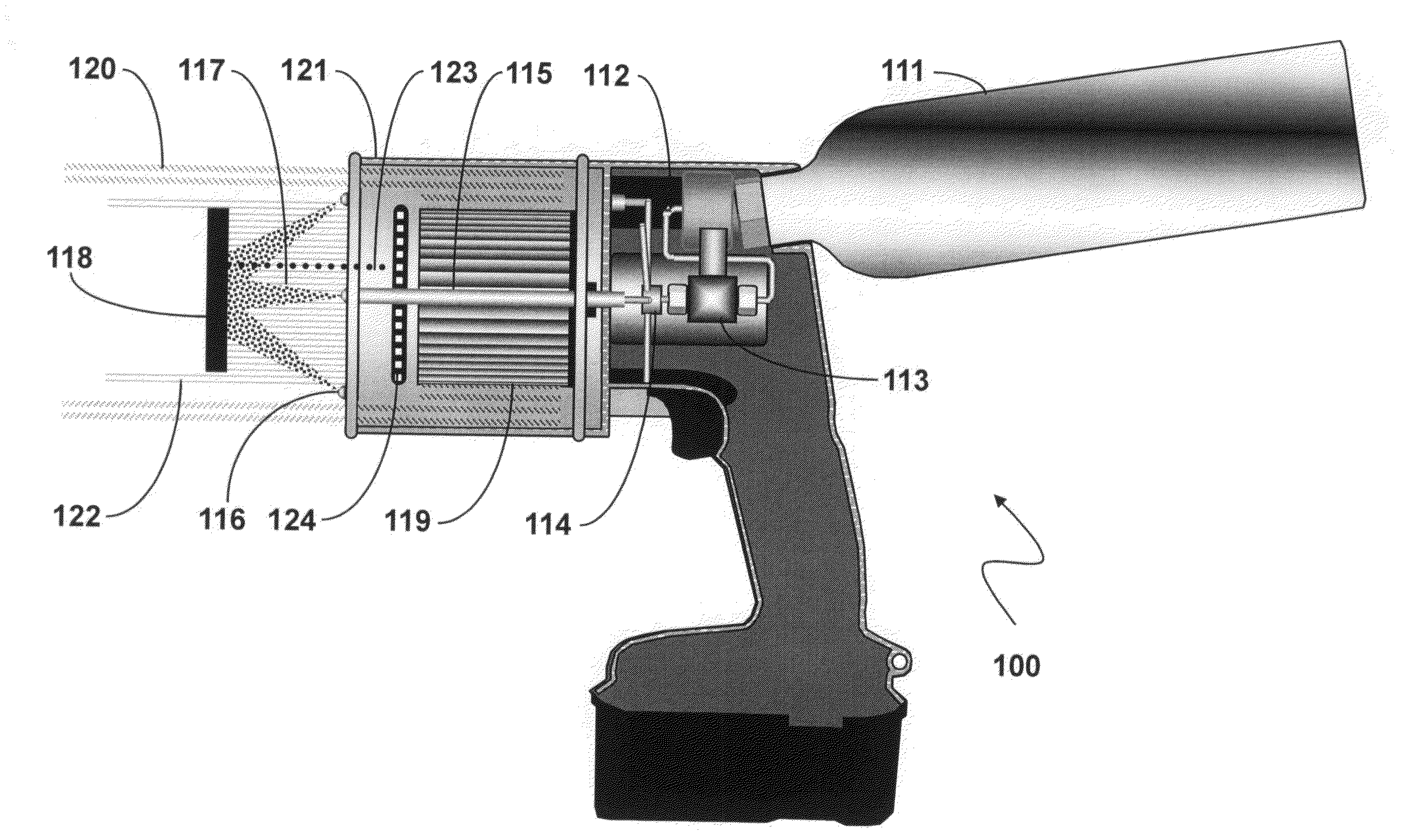
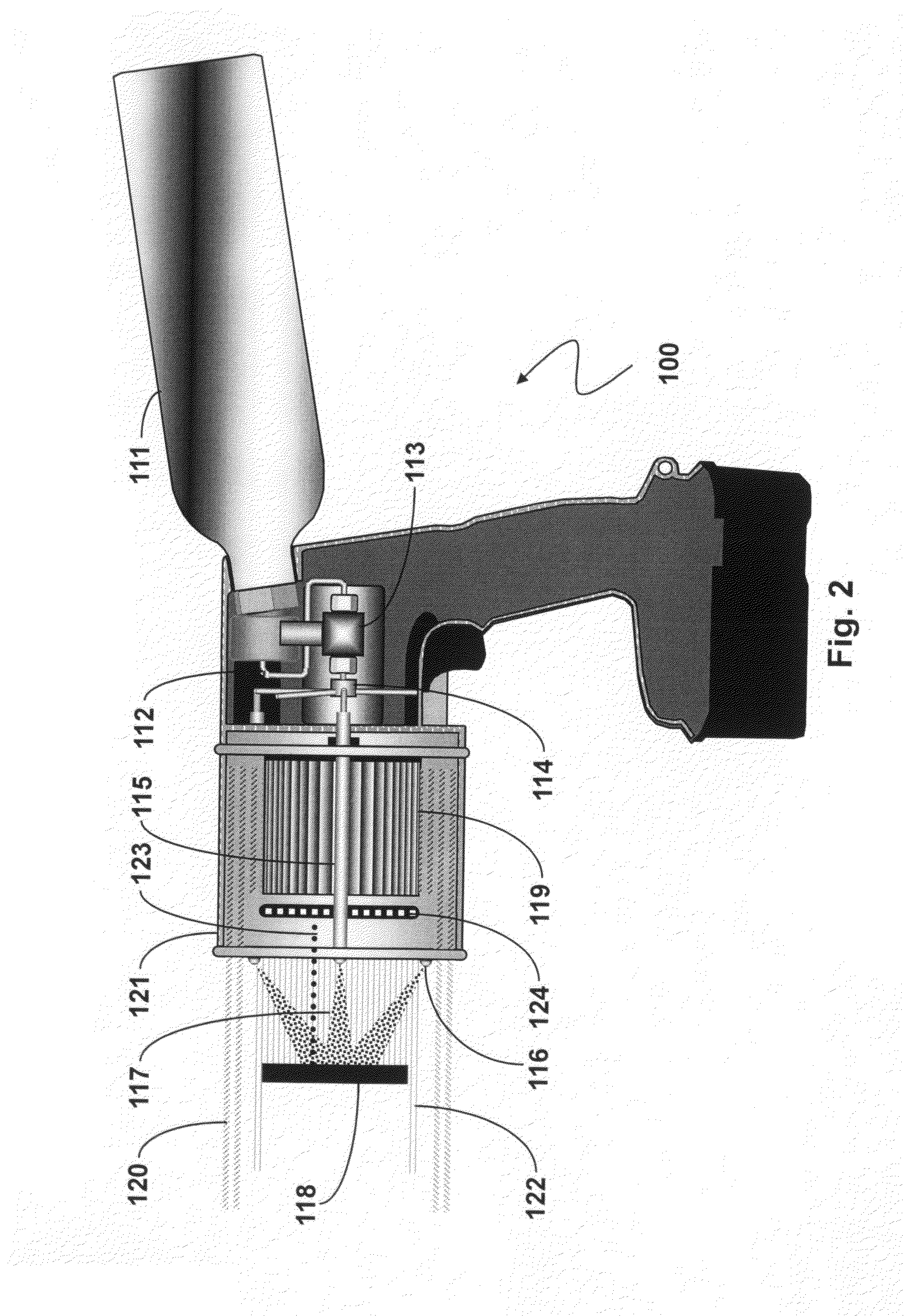
[0028]Referring now to FIG. 2, shown is an example of a trace particle collection system that may be used in connection with the particle removal system methods described herein. While various embodiments may differ in details, FIG. 2 shows basic features of the system described herein. The particle collection system 100 illustrated in FIG. 2 is a handheld portable system, but the principles may be applied to larger, non-mobile systems. The particle removal portion of the system consists of a reservoir of liquid carbon dioxide 111, a connection tube 112, a pulsed valve 113, an expansion chamber 114, a connection tube 115 to a nozzle 116, and a spray 117 of the aerosol mixture containing frozen carbon dioxide particles and pressurized gas against the target surface 118. The particle transport portion of the system consists of an impeller fan 119 configured as a vortex attractor. The fan 119 blows an outward flowing stream of air 120 that is spinning about the axis of the impeller fan...

second embodiment

[0038]Referring now to FIG. 3, shown is an example of a trace particle collection system that may be used in connection with the particle removal system methods described herein. While various embodiments may differ in details,

[0039]FIG. 3 shows basic features of the system described herein. The particle collection system 200 illustrated in FIG. 3 is a handheld portable system, but the principles may be applied to larger, non-mobile systems. The particle removal portion of the system consists of a reservoir of liquid carbon dioxide 211, a connection tube 212, a pulsed valve 213, an expansion chamber 214, a connection tube 215 to a nozzle 216, and a spray 217 of the aerosol mixture containing frozen carbon dioxide particles and pressurized carbon dioxide gas against the target surface 218. The particle transport portion of the system consists of an impeller fan 219 configured as a vortex attractor. The fan 219 blows an outward flowing stream of air 220 that is spinning about the axis...

third embodiment

[0042]Referring now to FIG. 4, shown is an example of a trace particle collection system that may be used in connection with the particle removal system methods described herein. While various embodiments may differ in details, FIG. 4 shows basic features of the system described herein. The particle collection system 300 illustrated in FIG. 4 is a handheld portable system, but the principles may be applied to larger, non-mobile systems. The particle removal portion of the system consists of a reservoir of liquid carbon dioxide 311, a connection tube 312, a pulsed valve 313, an expansion chamber 314, a connection tube 315 to a nozzle 316, and a spray 317 of the aerosol mixture containing frozen carbon dioxide particles and pressurized carbon dioxide gas against the target surface 318. The particle transport portion of the system consists of an impeller fan 319 configured as a vortex attractor. The fan 319 blows an outward flowing stream of air 320 that is spinning about the axis of t...


PUM

PropertyMeasurementUnit
pressureaaaaaaaaaa
suctionaaaaaaaaaa
atmospheric pressureaaaaaaaaaa

Abstract

A trace particle collection system accumulates trace particles of those materials that are adhering to target surfaces. The particles are removed from the surface, transported and collected in a particle collection medium, and then provided to a detection instrument. Trace particles are often bound tenaciously to the target surface, and simple techniques, such as blowing air, will either remove only the largest particles or none at all. The removal of trace particles is described which utilizes an aerosol mixture of frozen carbon dioxide aerosol particles in a gas stream to impact and more efficiently remove the target particles from the surface.

Description

BACKGROUND OF THE INVENTION[0001]1. Field of the Invention[0002]This invention relates to detection of trace chemicals, and more particularly to collection of particles of substances from a surface in order to provide the release, transport, and capture of the particles.[0003]2. Description of Related Art[0004]There exist a wide variety of chemical analysis instruments that are capable of detecting and identifying target particles of trace chemicals (“target chemicals”) once the sample of particles is transported to the instrument and subsequently vaporized. Examples include, but are not limited to, ion mobility spectrometers, mass spectrometers, gas chromatographs, surface acoustic wave sensors, cantilever beam sensors, and electron capture detectors. Similarly, there are several ways that may be utilized to transport the target particles to the instrument, some of which are incorporated within the instrument and some which may require an operator to perform the transfer. Examples ...

Claims


Application Information

Patent Timeline
Patent Type & Authority Applications(United States)
IPC IPC(8): G01N1/22
CPCB08B7/0092G01N1/22G01N1/02B24C1/003
Inventor BUNKER, STEPHEN N.
Owner LEIDOS SECURITY DETECTION & AUTOMATION INC
Why Eureka
Try Eureka