
Wind power plant having an adjustable power reserve

a technology of wind power plants and power reserves, which is applied in the direction of electric generator control, machine/engine, greenhouse gas reduction, etc., can solve the problems of inability to easily increase the maximum power capability of individual wind energy installations in the wind farm, inability to adjust the maximum power capacity of individual wind energy installations, and high cost of setting up and operating these power stations, so as to reduce the actuation activity of pitch drives, the regulation of power reserves is stable, and the effect of high regulation stability

Active Publication Date: 2012-06-07
SIEMENS GAMESA RENEWABLE ENERGY SERVICE GMBH
View PDF6 Cites 25 Cited by
  • Summary
  • Abstract
  • Description
  • Claims
  • Application Information

AI Technical Summary

Benefits of technology

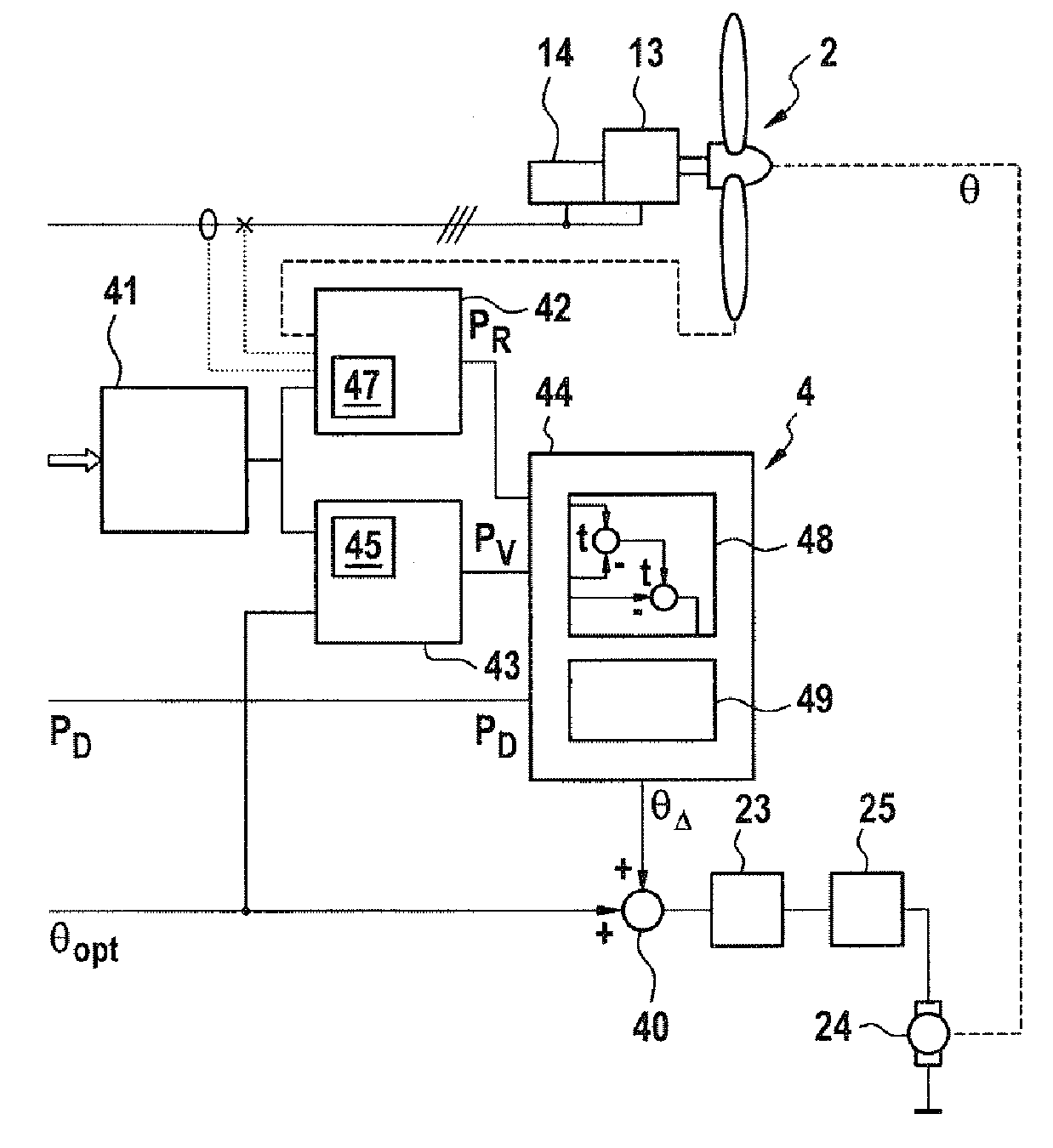
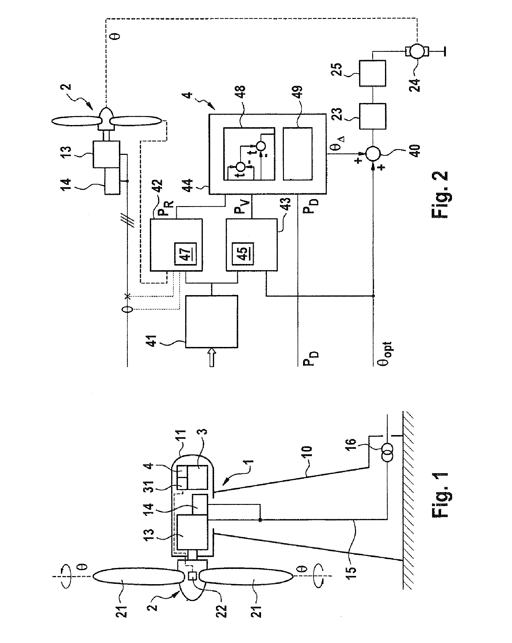
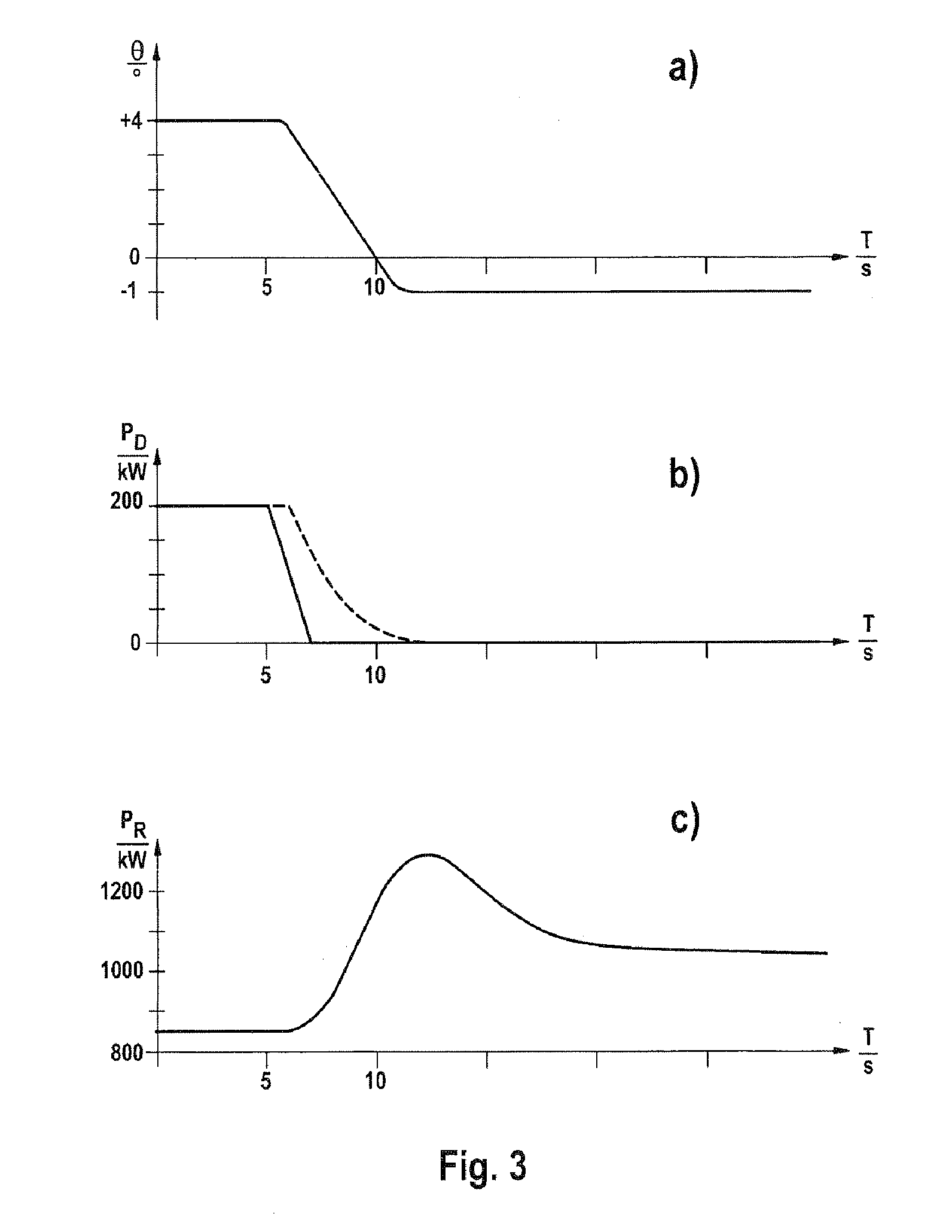
[0012]A further advantage of the invention is the high regulation stability. Surprisingly, it has been found that although the regulation is now only indirect (specifically via the offset of the pitch angle) as a result of the action on the pitch angle, instead of direct variation of the required nominal power, measurement errors and measurement inaccuracies in the input signals (in particular resulting from unavoidable measured value noise) have a much lesser effect, however, than when the power is directly preset, as known from the prior art. The regulation of the power reserve is therefore more stable and, because the actuation activity of the pitch drive is reduced owing to the reduced influence of the noise, it is also more protective in operation. Nevertheless, the regulation is sufficiently fast, despite this indirectness. This applies in particular to use as secondary regulation, which until now was highly problematic for wind energy installations.—Finally, it should also be noted that the required additional complexity is low. The required regulators and detectors can be implemented with little complexity in the operation controller and, because of the protective indirect regulation, the actuating drive for the pitch angle does not need to be additionally reinforced.
[0013]A wind estimation module is preferably provided for the detector and is designed to determine the available power by means of a model on the basis of the estimated wind speed. A model-based estimate of the wind speed such as this avoids inaccuracies and disturbances, such as those which are included in a real measurement by means of an anemometer. Surprisingly, it has been found that the data obtained is of considerably higher quality for determination of the available power, in particular because its noise spectrum is very much reduced in comparison to real measured values. Continuing this idea, a determination element for the actually produced power is preferably designed such that it is likewise model-based. This makes it possible to also achieve the same advantages with respect to the actually produced power. According to a further aspect, it is particularly preferable to use the same model as the basis for both the estimation of the available power and for the actually produced power. In particular, this offers the advantage that certain model errors (which are virtually unavoidable because of the simplifications required for the model) partially cancel one another out. This therefore results in a form of common-mode suppression, as a result of which the overall modeling has considerably better long-term stability. This also makes it possible to manage with relatively simple models, thus making it possible to avoid the difficulties, in particular stability problems, which frequently occur with complex models.
[0014]The use of a closed formula has been found to provide expedient modeling, with the total power being determined from the overall efficiency, the air density, the rotor circle area, the high running speed and the pitch angle, taking account of the third power of the estimated wind speed. A closed formula such as this allows accurate calculation without recursions. Alternatively, however, it is also possible to provide a look-up table (LUT). In particular, this offers the advantage of a high processing rate.
[0015]Expediently, the dynamic offset module comprises an I regulator. This offers the advantage of high steady-state accuracy. Any noise in the input signals is highly damped thanks to the integration, thus correspondingly protecting the actuating drive for the pitch angle. Thanks to the concept according to the invention of indirect control via the pitch angle, an I regulator such as this is also sufficiently fast that there is no need for a P element. However, the possibility of providing the regulator with an additional P component and D component should not be precluded.
[0016]In a wind farm having a plurality of wind energy installations, at least one of which has the determination of the regulation power according to the invention, it is expedient for this determination to be carried out by the farm master. This has the advantage of central processing, which is advantageous particularly when a plurality of wind energy installations are supplied with corresponding values for the regulation power. A balance module is expediently provided for this purpose in the farm master. This is designed to distribute the total regulation power required by the wind farm between the individual wind energy installations. For this purpose, the balance module preferably has a weighting unit, which is designed to provide the proportion of the respective wind energy installation on the basis of the rating of the individual wind energy installation.
[0017]However, it is also possible to design the balance module to operate individual wind energy installations in the wind farm in a coasting mode, and for these to be used for the regulation power. In this case, a coasting mode means that, although a wind energy installation is rotating, it does not produce any real power, or only a very small amount (a power of ten less than the others). These wind energy installations are then used for the regulation reserve, since the power actually demanded from them can be greatly increased. This concept is particularly advantageous when very different wind conditions occur across the farm, in a wind farm, the result of which is that wind energy installations in weak wind zones can be used well to provide the regulation reserve and, in the process, reductions in the actually produced real power during normal operation can be minimized. However, in order to unify the load, it is also possible for the regulation power to be distributed on the basis of the availability of the installations.

Problems solved by technology

Since frequency changes such as these are undesirable, their occurrence is reacted to by feeding in additional power (if the frequency is low) or reducing the power fed in (if the frequency is high).
The setting up and operation of these power stations is very expensive (particularly in the second reserve area).
One particular difficulty in this case is that, although wind energy installations can reduce their power output (DE 100 22 974 A1), it is not easily possible to increase their power—in contrast to conventional power stations—since the maximum available power is restricted by the available wind, and therefore fluctuates stochastically.
This quite simple concept in principle works, but has the disadvantage that discrepancies in the maximum power capability between the individual wind energy installations in the wind farm are not taken into account by the conditions found at the reference installation.
There is therefore no guarantee that the desired regulation power will also actually be available, and in fact this is random.
One advantage of the method is high transparency in its own right, but it has the disadvantage that errors in the measurement of the wind speed are passed through in their entirety to the result.
This has a particularly serious effect, because the measurement of the wind speed at the wind energy installation by means of an anemometer arranged on the nacelle is known to be imprecise.
Because of this, instabilities may occur, particularly when the discrepancies accumulate over a relatively long time period.
This admittedly makes it possible to mobilize additional power very quickly, virtually independently of the currently prevailing wind conditions, but this is at the expense of a falling rotor rotation speed, and can therefore be carried out only over a short time period.
One disadvantage of the method is that, because the pitch angle is reduced statically by a fixed amount, different power reserves result, depending on the installation operating point.
While this may still be acceptable for the primary regulation in the seconds area (since the operating point normally does not vary or varies only slightly over a few seconds), a response such as this is significantly disadvantageous for the secondary regulation, which relates to a longer time period.

Method used


Image

  • Wind power plant having an adjustable power reserve
  • Wind power plant having an adjustable power reserve
  • Wind power plant having an adjustable power reserve

Examples


Embodiment Construction

[0024]A wind energy installation 1 according to one exemplary embodiment of the invention comprises a tower 10 at whose upper end a nacelle 11 is arranged such that it can pivot in the azimuth direction. A wind rotor 2 is arranged such that it can rotate on an end face of the nacelle 11. Via a rotor shaft, this wind rotor 2 drives a generator 13, which converts the mechanical power produced by the rotor 2 to electrical power. In the illustrated exemplary embodiment, the generator 13 is in the form of a doubly-fed asynchronous machine, which is connected via a stator directly to a connecting line 15, and by its rotor via a converter 14 indirectly to the connecting line 15. The connecting line 15 leads to an installation transformer 16, which is preferably arranged in the area of the foot of the tower 10. The installation transformer 16 is connected to a power transmission grid system, with this generally being an internal grid system for a wind farm. An operation controller 3 is furt...


PUM


Abstract

A wind power plant, including a generator driven by a rotor in order to generate electrical power and a controller that includes a pitch module for adjusting a pitch angle of blades of the rotor. The controller has an input for a required power reserve and determines a target pitch angle depending on an operating point of the wind power plant. A secondary pitch controller is also provided, which includes a detector for available power and a dynamic offset module. Input signals for the available reserve power determined by the detector, the required reserve power and the generated electrical power are applied to the dynamic offset module, which is designed to determine a value for a pitch angle offset. An activation element varies the target pitch angle by the pitch angle offset.

Description

CROSS-REFERENCE TO RELATED APPLICATIONS[0001]This application is a national stage application under 35 USC 371 of International Application No. PCT / EP2010 / 004931, filed Aug. 12, 2010 which claims the priority of German Patent Application No. 10 2009 037 239.3, filed Aug. 12, 2009, the contents of which prior applications are incorporated herein by reference.FIELD OF THE INVENTION[0002]The invention relates to a wind energy installation having a generator, which is driven by a rotor, for producing electrical power. To be more precise, the invention relates to a wind energy installation having a rotor, which has variable-pitch blades and whose pitch angle is controlled by a wind energy installation controller. In this case, the controller determines the pitch angle to be set as a function of an operating point of the wind energy installation and an applied input signal for a power reserve to be maintained.BACKGROUND OF THE INVENTION[0003]As wind energy installations become increasingl...

Claims


Application Information

Patent Timeline
IPC IPC(8): H02P9/04
CPCF03D7/0224F03D9/02Y02E10/723F05B2270/703F05B2270/1033F03D9/10F03D9/257Y02E10/72Y02E70/30
Inventor KRUEGER, THOMAS
Owner SIEMENS GAMESA RENEWABLE ENERGY SERVICE GMBH
Learn More