Method for performing burn-in test

a technology for burnin test and burnin head, which is applied in the direction of mounting head within the housing, semiconductor operation lifetime testing, instruments, etc., can solve the problems of difficult contact between power supply probes, difficult to bring power supply probes into contact, and long time-consuming burnin test, so as to achieve stable and reliable burnin test, the reliability evaluation process can be significantly reduced, and the surface roughness is high

Active Publication Date: 2012-06-07
TDK CORPARATION +1
View PDF1 Cites 21 Cited by
  • Summary
  • Abstract
  • Description
  • Claims
  • Application Information

AI Technical Summary

Benefits of technology

[0032]In the method for performing a burn-in test according to the present invention, the sheet-type probes can be kept in stable contact with electrodes on a unit bar on which multiple electrodes are provided in positions at different heights, because electrodes in a higher position have a higher surface roughness Ra than electrodes in a lower position. Consequently, stable and reliable burn-in test can be performed. In addition, the multiple laser diodes on the unit bar can be evaluated at a time before the unit bar is diced into individual light-source-unit chips. The simultaneous process enables burn-in test to be performed on a large number of laser diodes at a time, and therefore the man-hours and time required for the reliability evaluation process can be significantly reduced.

Problems solved by technology

However, the burn-in test takes very long time, for example several to several tens of hours, per laser diode.
However, it is extremely difficult to bring power-supply probes into contact with an enormous number of electrodes for multiple laser diodes provided on a unit bar at a time.
However, the needles are expensive and, in addition, if a single needle on the card fails to make contact, all needles on the card need to be replaced, which is very uneconomical.
Furthermore, when needles are brought into contact with upper electrodes of laser diodes, excessive mechanical stress can be applied to the laser diodes.
However, it is very difficult to stably supply power with individual electrodes for laser diodes with sheet-type probes.
Accordingly, there has been a problem that when sheet-type probes are brought into contact with an electrode on a laser diode and an electrode on a unit substrate which significantly differs in height, the angle at which the sheet-type probes makes contact with the electrode on the laser diode is relatively shallow and therefore the contact between the electrode on the laser diode and the sheet-type probe becomes unstable.
Therefore, when a sheet-type probe makes contact with the electrode on the laser diode at a shallow angle, the contact between the sheet-type probe and the electrode is unstable.

Method used


Image

  • Method for performing burn-in test
  • Method for performing burn-in test
  • Method for performing burn-in test

Examples


Embodiment Construction

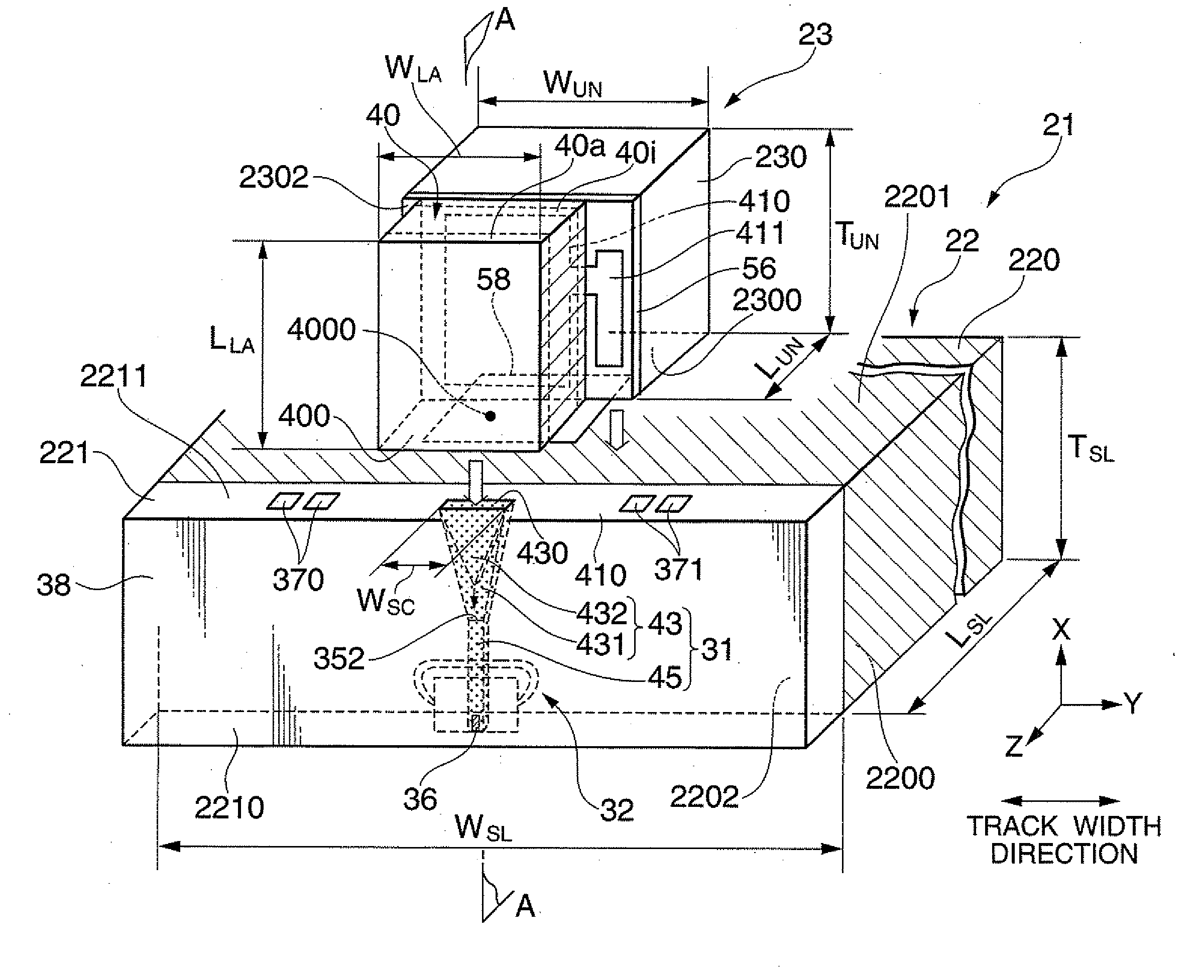
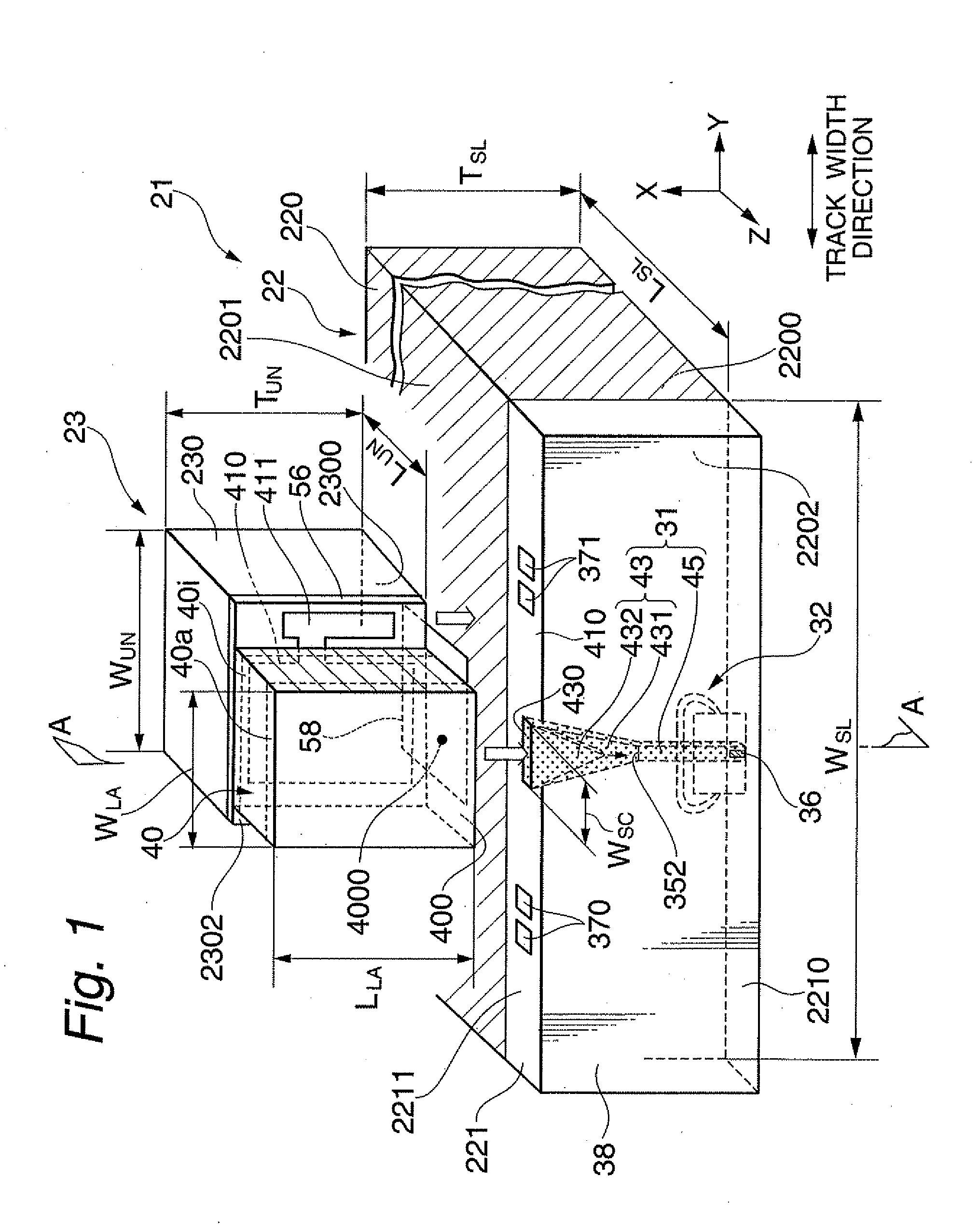
[0050]FIG. 1 shows a perspective view illustrating one embodiment of a thermally-assisted magnetic recording head according to the present invention.

[0051]As shown in FIG. 1, a thermally-assisted magnetic recording head 21 is fabricated by aligning and joining a light source unit 23, which includes a laser diode 40 as a light source for thermal assist, and a slider 22, which includes an optical system 31.

[0052]The slider 22 includes: a slider substrate 220 having an air bearing surface (ABS) 2200 processed so as to provide an appropriate flying height; and a head element part 221 that includes an optical system 31 and is formed on an element-integration surface 2202 that is perpendicular to and adjacent to the ABS 2200. While, the light source unit 23 includes: a unit substrate 230 having an joining surface 2300; and a laser diode 40 as a light source provided on a source-installation surface 2302 that is perpendicular to and adjacent to the joining surface 2300.

[0053]These slider 2...


PUM


Abstract

Provided is a method for performing a burn-in test on an object under test in which a plurality of electrodes are provided in positions at different heights. The method comprising steps of: preparing an object under test in which an electrode in a higher position have a higher surface roughness among the plurality of electrodes; bringing a plurality of sheet-type probes into contact with the plurality of electrodes, respectively; and supplying an electric current with the plurality of electrodes through the plurality of sheet-type probes. By implementing the method, the sheet-type probes can be kept in stable contact with the electrodes because electrodes in a higher position have a higher surface roughness Ra than electrodes in a lower position. Consequently, stable and reliable burn-in test can be performed.

Description

BACKGROUND OF THE INVENTION[0001]1. Field of the Invention[0002]The present invention relates to a method for performing burn-in test which is a current-carrying test effective for screening target elements. The present invention especially relates to a burn-in test applied to a light source unit that includes a light source for thermally-assisted magnetic recording, and to a test apparatus for performing the burn-in test.[0003]2. Description of the Related Art[0004]With the explosion in the use of the Internet in these years, a huge amount of data that are incommensurably larger than ever are stored and used on computers such as servers and information-processing terminals. This trend is expected to further grow at an accelerated rate. Under these circumstances, demand for magnetic recording apparatuses such as magnetic disk apparatuses as mass storage is growing, and the demand for higher recording densities of the magnetic recording apparatuses is also escalating.[0005]In the mag...

Claims


Application Information

Patent Timeline
Patent Type & Authority Applications(United States)
IPC IPC(8): G01R31/00
CPCG01R31/2635G01R31/2642G11B5/105G11B5/3166H01S5/0042G11B2005/0021H01S5/0021G11B5/455G11B5/3173
Inventor SHIMAZAWA, KOJIKANEKO, MASAAKIHONDA, TAKASHIMUGINO, YOICHINISHIOKA, YOSHITONOMA, TSUGUKI
Owner TDK CORPARATION
Why Eureka
Try Eureka