Power supply and arc processing power supply
- Summary
- Abstract
- Description
- Claims
- Application Information
AI Technical Summary
Benefits of technology
Problems solved by technology
Method used
Image

Examples
example of first embodiment
[0018]An arc processing machine according to a first exemplary embodiment of the present invention will now be described with reference to the drawings.
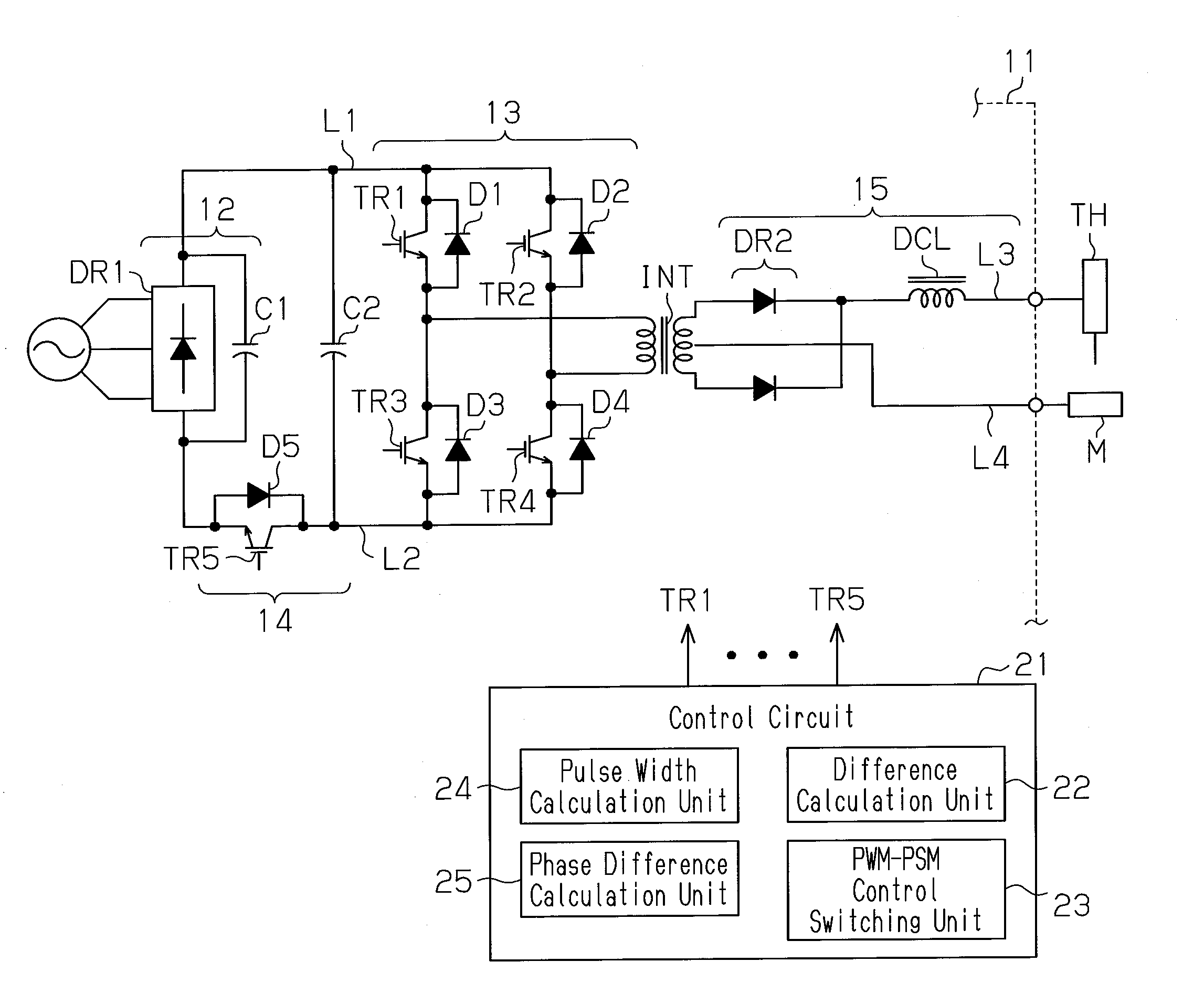
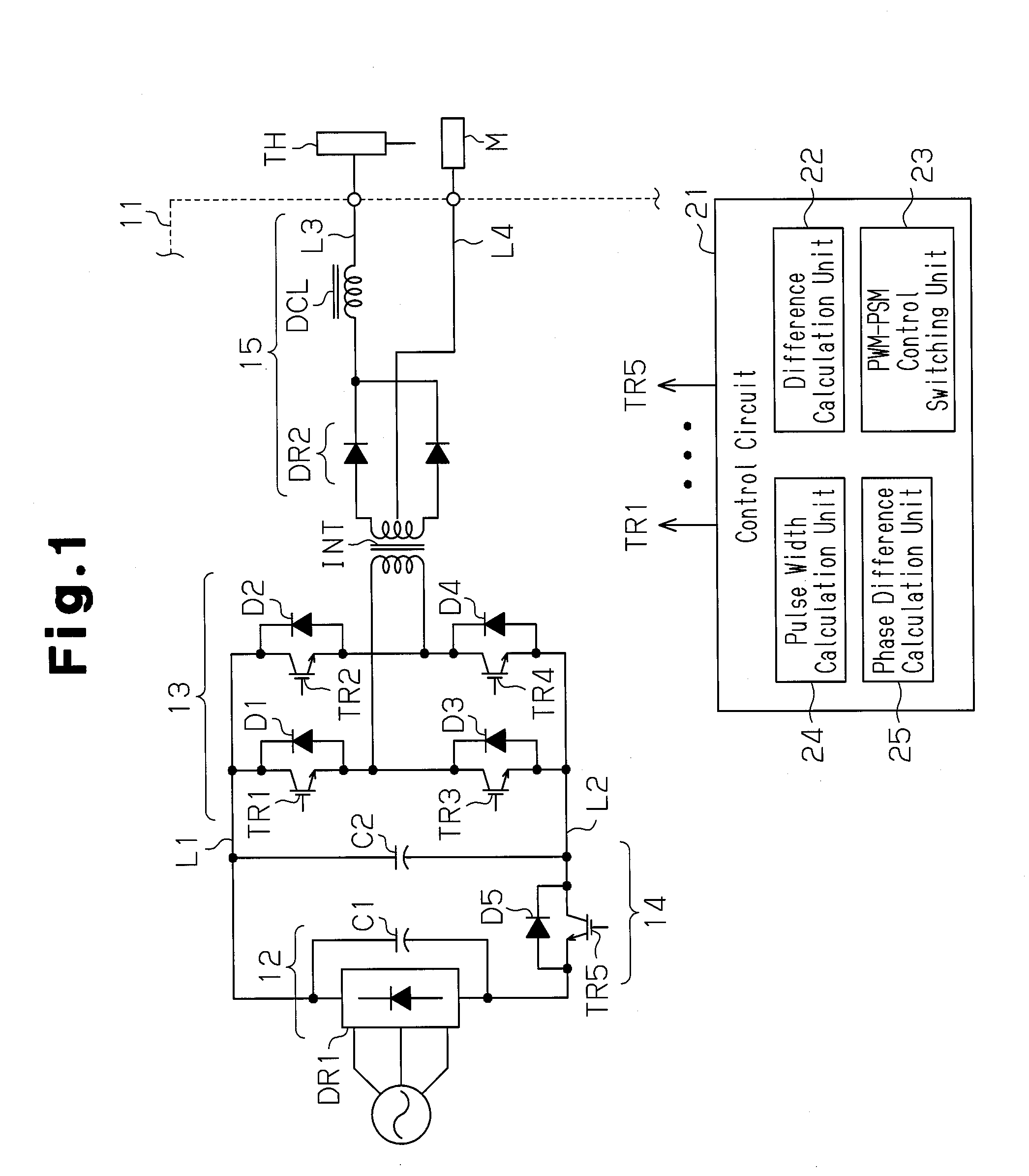
[0019]As shown in FIG. 1, the arc processing machine includes an arc processing power supply 11 that generates output voltage, which is supplied to a torch TH. This generates an arc directed from the torch TH to a processing subject M to perform arc processing, such as arc welding or arc cutting, on the processing subject M.
[0020]The power supply 11 includes a DC conversion circuit 12, an inverter circuit 13, an auxiliary switching circuit 14, a transformer INT, and an output conversion circuit 15. The DC conversion circuit 12 includes a rectification circuit DR1, which is formed by a diode bridge, and a smoothing current Cl. The DC conversion circuit 12 converts three-phase input AC power, which is supplied from a commercial power supply, to DC power. Further, the DC conversion circuit 12 supplies the converted DC power to the inver...
example of second embodiment
[0081]A second exemplary embodiment of the present invention will now be described with reference to the drawings. In the present exemplary embodiment, the power supply 11 shown in FIG. 1 performs the control shown in FIG. 4 with the control circuit 21.
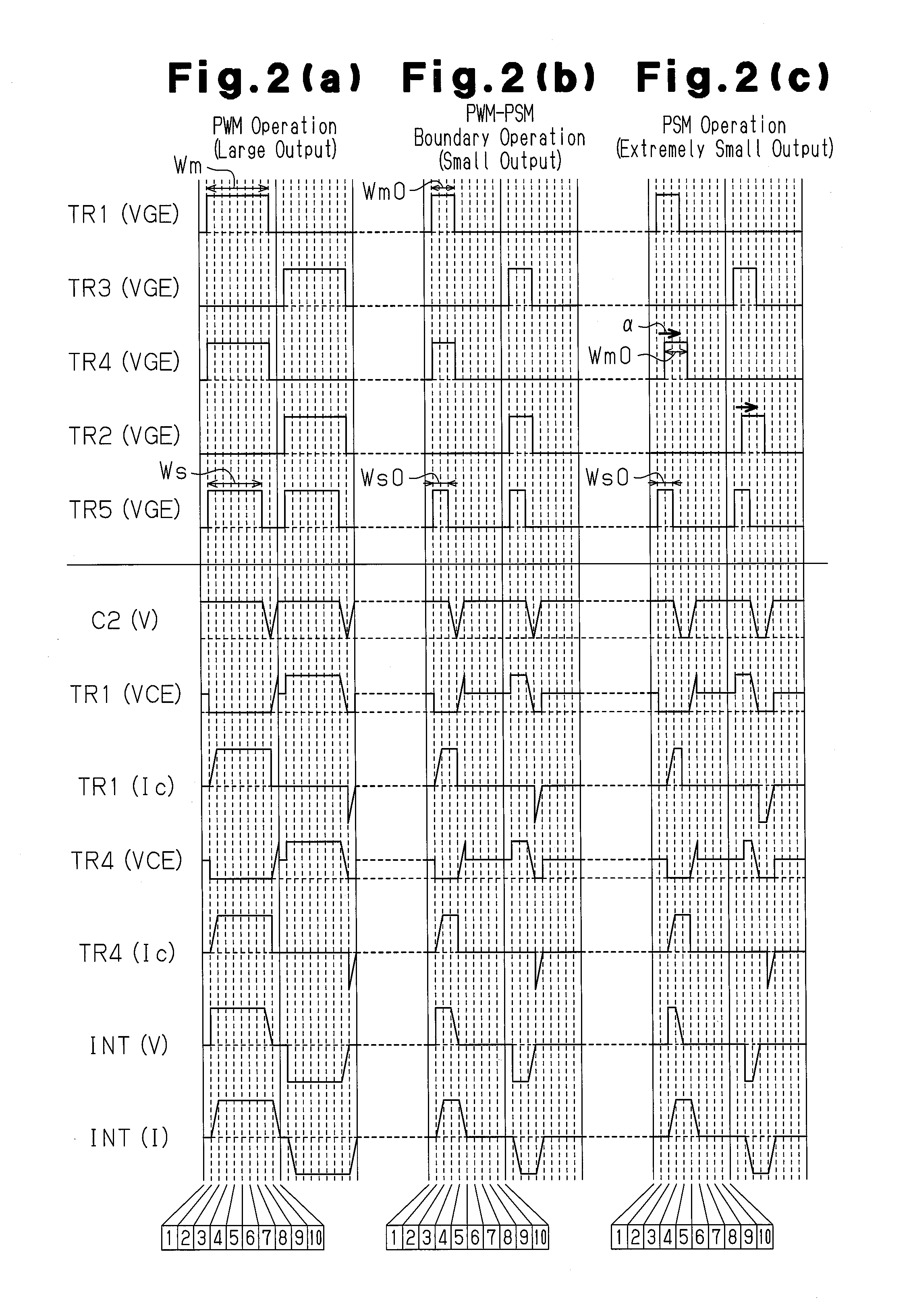
[0082]As shown in FIGS. 4(a) and 4(b), during a period in which PWM control is performed when a large output or small output is required, PWM control is performed by changing the ON pulse width Wm of the two control pulse signals for the switching elements TR1 and TR4 of the same set in the inverter circuit in the same manner as the first exemplary embodiment and also by changing the ON pulse width Wm of the two control pulse signals for the switching elements TR2 and TR3 in the same manner. The control pulse signal output to the switching element TR5 of the auxiliary switching circuit 14 rises at the same time as the control pulse signal output to the inverter circuit 13 and falls before the control pulse signal output to the inverte...
example of third embodiment
[0089]A third exemplary embodiment of the present invention will now be described with reference to the drawings. The present exemplary embodiment slightly differs from the second exemplary embodiment in the control that is performed as shown in FIG. 5.
[0090]As shown in FIG. 5, regardless of whether the PWM control or PSM control is performed, the ON pulse width Wm of the control pulse signals output to the switching elements TR1 and TR3 of the inverter circuit 13 corresponding to the reference phases and are constantly fixed to the maximum width Wmx. During PWM control, the ON pulse width Wm of the control pulse signals for the switching elements TR4 and TR2 corresponding to the control phases are changed. During PSM control, the phase of the control pulse signal output to the auxiliary switching circuit 14 is adjusted.
[0091]The present example of the third embodiment has the advantages described below.
[0092](1) The present exemplary embodiment stabilizes output when an extremely s...
PUM
 Abstract
Description
Claims
Application Information
 - Generate Ideas
- Intellectual Property
- Life Sciences
- Materials
- Tech Scout
- Unparalleled Data Quality
- Higher Quality Content
- 60% Fewer Hallucinations
Browse by: Latest US Patents, China's latest patents, Technical Efficacy Thesaurus, Application Domain, Technology Topic, Popular Technical Reports.
© 2025 PatSnap. All rights reserved.Legal|Privacy policy|Modern Slavery Act Transparency Statement|Sitemap|About US| Contact US: help@patsnap.com