Eureka AIR delivers breakthrough ideas for toughest innovation challenges, trusted by R&D personnel around the world.

Distribution of optical power in an optical transport system

Inactive Publication Date: 2012-06-07
RPX CORP
View PDF19 Cites 12 Cited by
  • Summary
  • Abstract
  • Description
  • Claims
  • Application Information

AI Technical Summary

Benefits of technology

[0006]Disclosed herein are various embodiments of an optical-power-distribution (OPD) subsystem that provides means for supplying optical local-oscillator signals and optical-carrier signals to various optical line cards, without the need for each optical line card to have a corresponding individual laser source. In one embodiment, a single laser coupled to the OPD subsystem may provide optical local-oscillator signals and / or optical-carrier signals to multiple optical line cards. In another embodiment, multiple lasers coupled to the OPD subsystem may provide multiple optical local-oscillator signals and / or optical-carrier signals to a single line card. Advantageously, the OPD subsystem may provide significant power savings in the operation of the corresponding optical transport system, a reduction in the required equipment-cooling capacity, and / or an increase in the device-packing density within optical line cards and / or inside equipment cabinets that house optical line cards.

Problems solved by technology

During operation, the various devices of a line card may generate significant amounts of heat, which requires the use of cooling equipment and imposes an upper limit on the device-packing density in the line card and / or in the corresponding equipment cabinet or rack.

Method used


Image

  • Distribution of optical power in an optical transport system
  • Distribution of optical power in an optical transport system
  • Distribution of optical power in an optical transport system

Examples


Embodiment Construction

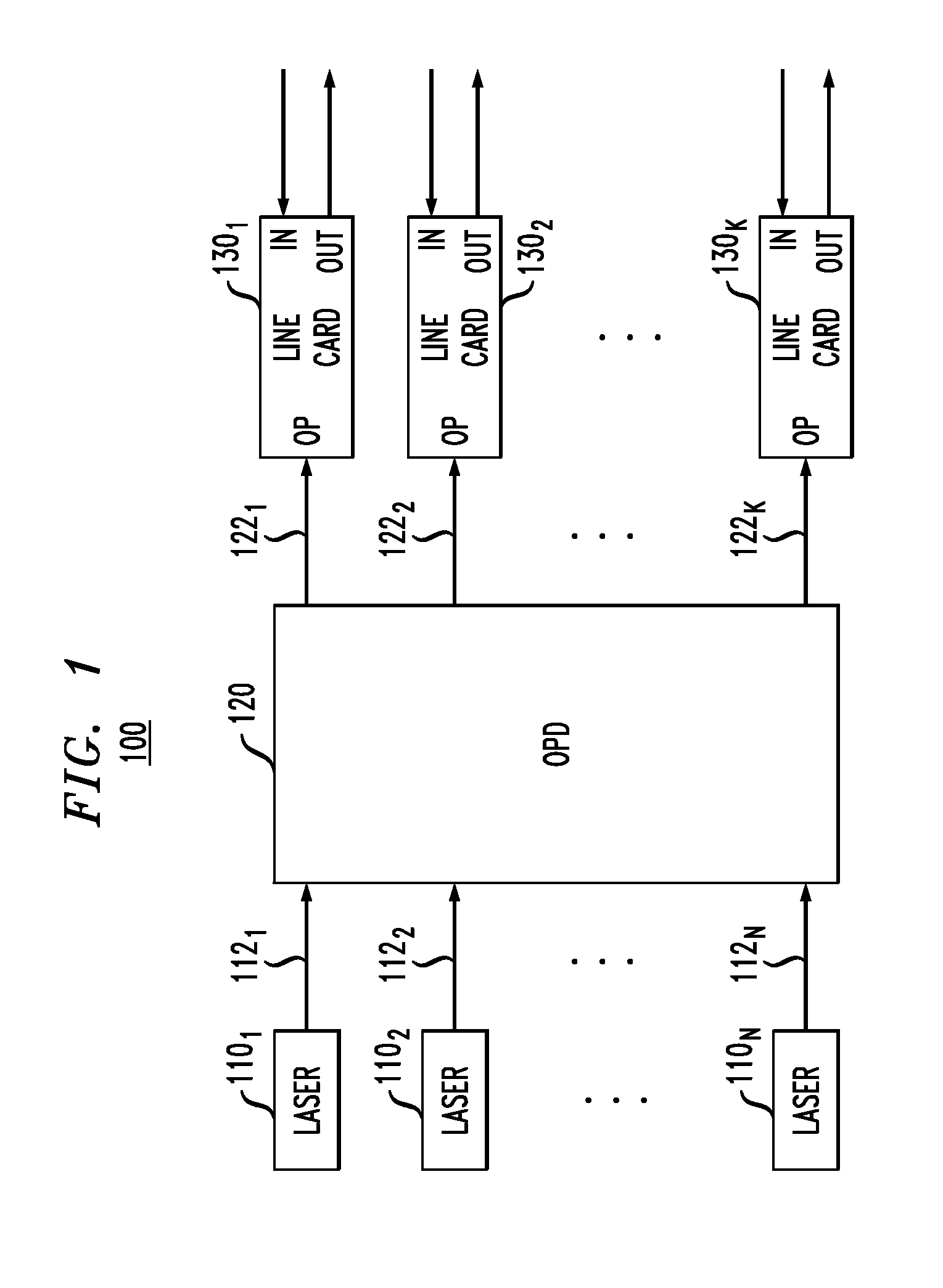
[0016]FIG. 1 shows a block diagram of an optical transport system 100 according to one embodiment of the invention. System 100 has a plurality of optical line cards 1301-130K configured to send and / or receive optical communication signals, where K is a positive integer greater than one. In a representative embodiment, an optical line card 130 has three optical ports that are labeled OP, IN, and OUT, respectively, in FIG. 1. Optical port OP serves to receive optical power generated by optical sources, such as lasers 1101-110N, that are external to the line card. Optical port IN serves to receive modulated optical signals from a remote transmitter (not explicitly shown in FIG. 1) for demodulation and decoding in line cards 130. Optical port OUT serves to output modulated optical signals produced in line card 130 for transmission to a remote receiver (not explicitly shown in FIG. 1). Although not explicitly shown in FIG. 1, each line card 130 also has one or more electrical ports, e.g....


PUM


Abstract

An optical-power-distribution (OPD) subsystem that provides means for supplying optical local-oscillator signals and optical-carrier signals to various optical line cards, without the need for each optical line card to have a corresponding individual laser source. In one embodiment, a single laser coupled to the OPD subsystem provides optical local-oscillator signals and / or optical-carrier signals to multiple optical line cards. In another embodiment, multiple lasers coupled to the OPD subsystem provide multiple optical local-oscillator signals and / or optical-carrier signals to a single line card. An OPD subsystem may provide significant power savings in the operation of the corresponding optical transport system, a reduction in the required equipment-cooling capacity, and / or an increase in the device-packing density within optical line cards and / or inside equipment cabinets that house optical line cards.

Description

BACKGROUND[0001]1. Field of the Invention[0002]The present invention relates to optical communication equipment and, more specifically but not exclusively, to the generation and distribution of optical power for use in optical line cards and other optical devices of an optical transport system.[0003]2. Description of the Related Art[0004]This section introduces aspects that may help facilitate a better understanding of the invention(s). Accordingly, the statements of this section are to be read in this light and are not to be understood as admissions about what is in the prior art or what is not in the prior art.[0005]An optical line card is used for interfacing optical communication lines, e.g., carrying optical signals to and from a central office to the rest of the telecommunication network's central offices. A typical optical line card is a modular opto-electronic circuit assembled on a printed circuit board. Its representative modules may include one or more optical-power sourc...

Claims


Application Information

Patent Timeline
IPC IPC(8): H04B10/02
CPCH04B10/61H04B10/2587
Inventor NEILSON, DAVID T.WINZER, PETER J.
Owner RPX CORP
Why Eureka
Eureka Blog
Learn More