
Method and apparatus for minimizing accumulation of polymer on process equipment, especially safety devices

a technology of safety devices and process equipment, applied in the direction of distillation, trickle coolers, coke oven details, etc., can solve the problems of affecting the proper functioning of process equipment, affecting the safety of workers, and forming and accumulating polymer. a common and troublesome occurrence, and the effect of reducing the risk of accidental accumulation

Inactive Publication Date: 2012-06-14
ROHM & HAAS CO
View PDF10 Cites 2 Cited by
  • Summary
  • Abstract
  • Description
  • Claims
  • Application Information

AI Technical Summary

Benefits of technology

This method effectively minimizes polymer accumulation on safety devices, ensuring their proper operation and the safe functioning of distillation columns by utilizing the moving liquid phase fluid to intermittently contact and remove polymerizable materials and condensate, thereby maintaining service-readiness and preventing unsafe conditions.

Problems solved by technology

This accumulation often interferes with the proper functioning of the process equipment by locking moving parts in static positions or restricting fluid flow required for proper functioning of the process equipment.
In particular, despite efforts to prevent formation of polymer during purification of polymerizable monomers in separation apparatus, such as a distillation column, the unwanted formation and accumulation of polymer is a common and troublesome occurrence.
For example, one type of polymerization, “condensation polymerization” which forms “condensation polymer,” is especially troublesome when distilling polymerizable monomers.
A particularly vexing and dangerous problem is the accumulation of polymer on and near safety equipment, such as pressure relief devices.
For example, the accumulation of polymer in and on mounting connections for pressure relief devices may result in an undesirable seal between the mounting connections and the pressure relief devices, impairing removal and replacement of the safety devices.
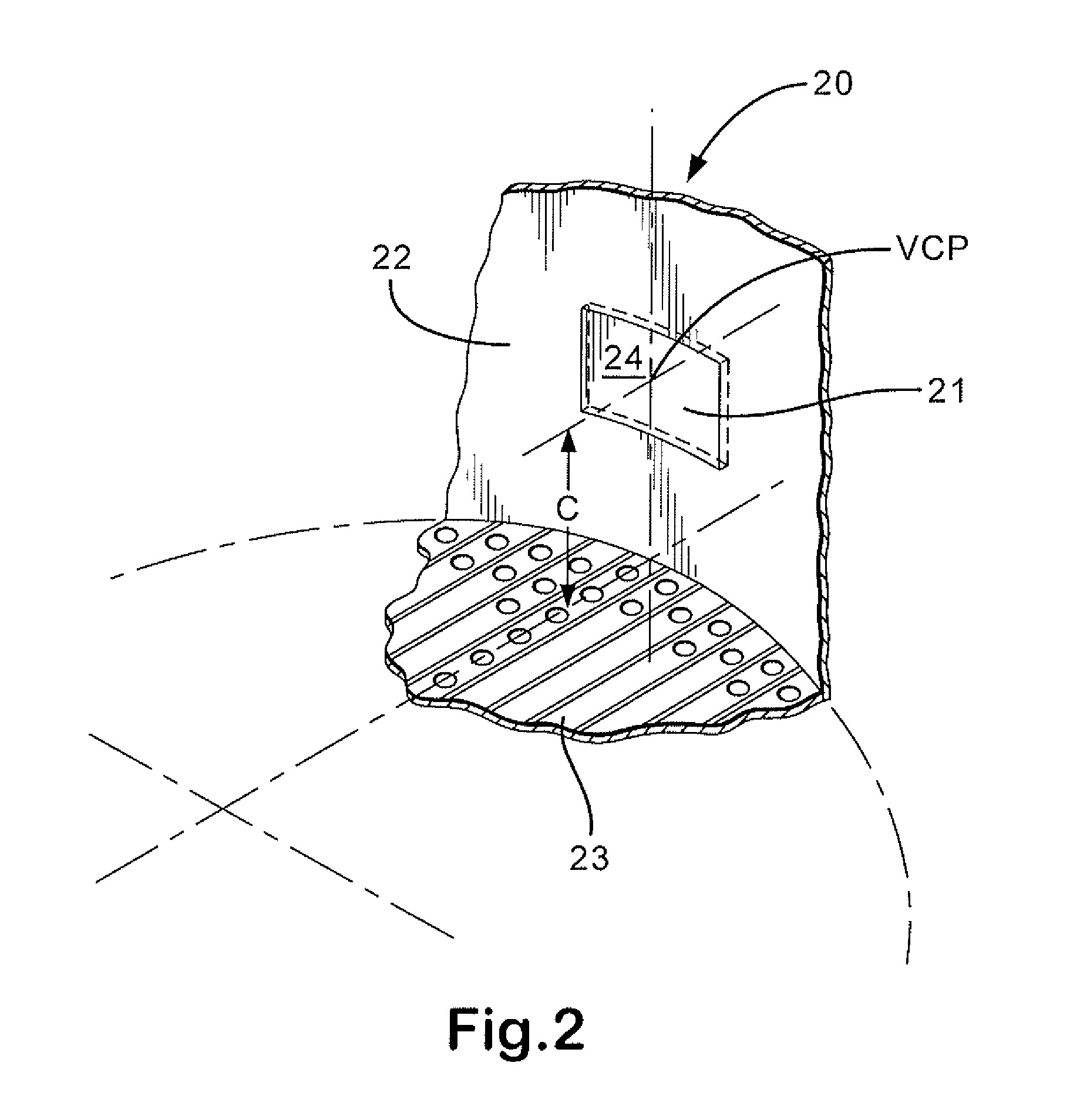
Additionally, polymer may accumulate upstream and proximate to the safety device, such as on the inner walls of a conduit or recessed region wherein the safety device is positioned.
Accumulation of polymer in either area tends to restrict the free flow of process fluid near and to the safety device and may, therefore, prevent the pressure relief from operating properly in response to process fluid pressure.
This situation limits the capacity of the pressure relief device and creates an unsafe condition.
Polymer may also adhere to the surfaces of the pressure relief devices themselves, preventing them from operating as intended—for example, polymer accumulation may cause relief valves to “stick” in the closed position or may cause rupture disks to fail to open at their intended burst pressure.
This approach is not effective, however, in low flow regions such as proximate to pressure relief device mounting connections, where the monomer vapors may stagnate and become trapped.
The efficacy of adding vapor-phase polymerization inhibitors, however, is limited because the fluid present in low flow regions, such as near nozzles, or in interior corners, is essentially stagnant and, therefore, poor mixing occurs and the inhibitors tend not to flow into these regions, whereby polymer formation and accumulation may proceed virtually unabated.
This approach fails, however, to adequately prevent the accumulation of material in small, low-flow regions, such as the pressure relief device mounting connections on the top head of the column and on the opposite-facing surfaces of process apparatus.
As mentioned below, additional spray devices may be used, but this approach introduces other difficulties.
However, the installation of the spray nozzle is mechanically complex as well as invasive to the vessel, requiring penetration of the vessel at a separate place on the vessel wall, and the positioning of the line(s) inside the vessel for supplying the liquid to the spray nozzle.
With this approach, the elevation and alignment of the spray nozzle itself, as well as the flow rate and spray pattern, are critical and, in practice, it is quite difficult to obtain the proper combination of these variables such that polymer accumulation is wholly prevented.
While the effectiveness of such an arrangement could be improved through the use of multiple spray nozzles and an overwhelmingly large quantity of liquid spray, such an approach is costly and impractical in commercial operations.
Another limitation of this approach is that it requires a continuous supply of flushing fluid to operate as intended.
If there is a significant interruption in the supply of flushing fluid, the benefit of the disclosed apparatus and method may not be maintained and the service-readiness of the pressure relief device may be compromised.
Additionally, the physical presence of the spray nozzle(s) and its supply line(s) create an undesirable obstruction in the process connection, thereby interfering with the free flow of material through the attached pressure relief device, as well as providing additional surfaces on the components themselves for the accumulation of condensation polymer.
In some instances, the direct impingement of pressurized spray liquid on the relief device may also cause mechanical fatigue, thereby shortening the service life of the device and leading to premature failures.
While the apparatus and method disclosed in U.S. Pat. No. 6,409,886 resolve many problems of the prior art, because of the above-stated limitations, this apparatus and method are impractical when applied, for example, to the small, low flow regions that lie upstream of pressure relief devices in distillation columns.

Method used


Image

  • Method and apparatus for minimizing accumulation of polymer on process equipment, especially safety devices
  • Method and apparatus for minimizing accumulation of polymer on process equipment, especially safety devices
  • Method and apparatus for minimizing accumulation of polymer on process equipment, especially safety devices

Examples


example 1

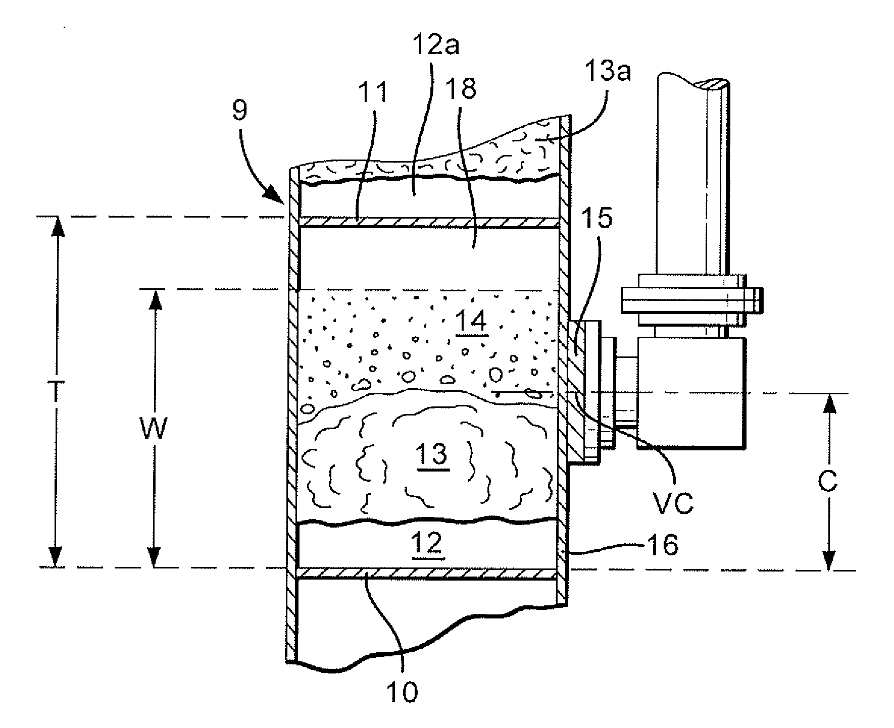
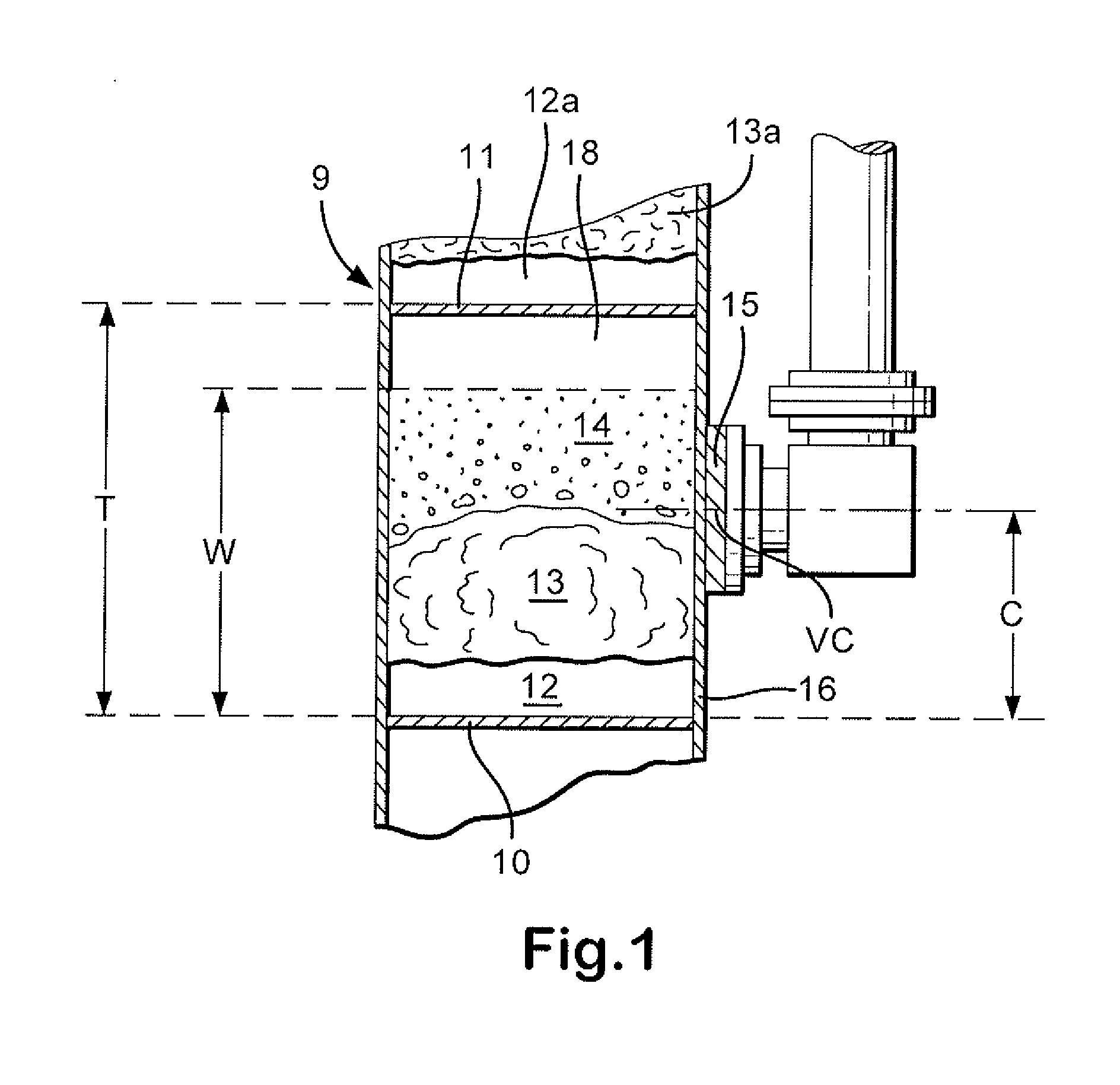
[0071]A pressure relief device was installed, in accordance with the present invention, in a commercial-scale distillation column comparable design to Comparative Example 1 and the column was again used in a process for purification of acrylic acid. As in Comparative Example 1, the pressure relief device was a rupture disc having a nominal burst pressure of 25 psig (1.7 atmospheres) and full-vacuum rating.

[0072]With reference collectively to FIGS. 6 and 7 the safety device assembly 60 having a rupture disk 61 was connected to the column wall 73 of the distillation column 74, in accordance with the method and apparatus of the present invention (see FIG. 7). More particularly, the safety device assembly 60 was positioned relative to the topmost tray 72, in a substantially vertical orientation, and at an elevation within the wetted region (not shown) present above the topmost tray 72. In this position and orientation of the safety device assembly 60, the froth / liquid spray (liquid phas...

example 2

[0083]A pressure relief device was installed, in accordance with the present invention, in a commercial-scale distillation column of comparable design to Comparative Example 2 and the column was again used in a process for purification of acrylic acid. The pressure relief device was a rupture disc having a nominal burst pressure of 15 psig (1 atmosphere) and full-vacuum rating.

[0084]With reference to FIG. 9, the safety device assembly was connected and positioned relative to the distillation column in accordance with the present invention, i.e., in a substantially vertical orientation, and at an elevation within the vertical extent W of the wetted region above the topmost tray of the distillation column, such that the froth / liquid spray (liquid phase fluid) present above the topmost tray intermittently contacted the upstream surface of the rupture disc, thereby preventing accumulation of unwanted polymer and condensate.

[0085]As shown schematically in FIG. 9, the distillation column ...


PUM

PropertyMeasurementUnit
tray spacingaaaaaaaaaa
spacingaaaaaaaaaa
spacingaaaaaaaaaa

Abstract

Accumulation of polymer on equipment, which is in contact with polymerizable material during normal process operation, is minimized by the method and apparatus of the present invention. The method comprises positioning and affixing the equipment, such as a pressure relief device, to process apparatus, such as a distillation column, proximate to a wetted region comprising liquid phase fluid in the process apparatus, such that the moving liquid phase fluid is at least intermittently in contact with the equipment and one or more of accumulated polymerizable material, condensate comprising same, and polymer, is washed off of the equipment. The apparatus of the present invention is effective for maintaining the service-readiness of the equipment, which provides for safe long-term operation of the process apparatus.

Description

FIELD OF THE INVENTION[0001]The present invention relates to a method for minimizing accumulation of polymer on process equipment, such as pressure relief devices, during chemical processes such as the production of polymerizable materials, for example, polymerizable monomers including, but not limited to, (meth)acrylic acid and its esters, vinyl chloride, hydrogen cyanide, (meth)acrylonitrile, (methyl)styrene, and other vinyl monomers. More particularly, the present invention relates to a method for preventing accumulation of polymer on process equipment by properly positioning and affixing such process equipment relative to components of other process apparatus and liquid phase fluids, for example, positioning and affixing a safety device proximate to a wetted region in an operating distillation column.BACKGROUND[0002]Processes for the production of polymerizable materials often involve process equipment on which polymer tends to accumulate during normal process operation. This ac...

Claims


Application Information

Patent Timeline
Patent Type & Authority Applications(United States)
IPC IPC(8): B08B9/032
CPCB01D3/16Y10S203/22B01D3/42Y10T137/043Y10T137/1692Y10T137/1812
Inventor BARNETT, JOHN O.DECOURCY, MICHAEL STANLEYHURLEY, MICHAEL W.
Owner ROHM & HAAS CO
Features
  • Generate Ideas
  • Intellectual Property
  • Life Sciences
  • Materials
  • Tech Scout
  • Unparalleled Data Quality
  • Higher Quality Content
  • 60% Fewer Hallucinations
Learn More