Plasma apparatus

Inactive Publication Date: 2012-06-14
IND TECH RES INST
View PDF9 Cites 3 Cited by
  • Summary
  • Abstract
  • Description
  • Claims
  • Application Information

AI Technical Summary

Benefits of technology

[0009]The disclosure is directed to a plasma apparatus, which may

Problems solved by technology

Regarding a current research and development status of displays, large-scale displays and flexible displays are researched and developed, and during a commercialisation process of the displays, a most important issue thereof is a high uniformity problem of a large area substrate.
Regarding conventional capacitively coupled plasma (CCP), a processing rate of the apparatus cannot be effectively improved due to a small density of the plasma, so that inductively coupled plasma (ICP) becomes a technique with a great potential.
However, a design of a large area ICP may have following problems: (1) when a length of the coil is excessively long to cause a problem of standing wave, efficiency of energy transfer is influenced; (2) in case of a large area, unifor

Method used


Image

  • Plasma apparatus
  • Plasma apparatus
  • Plasma apparatus

Examples


Embodiment Construction

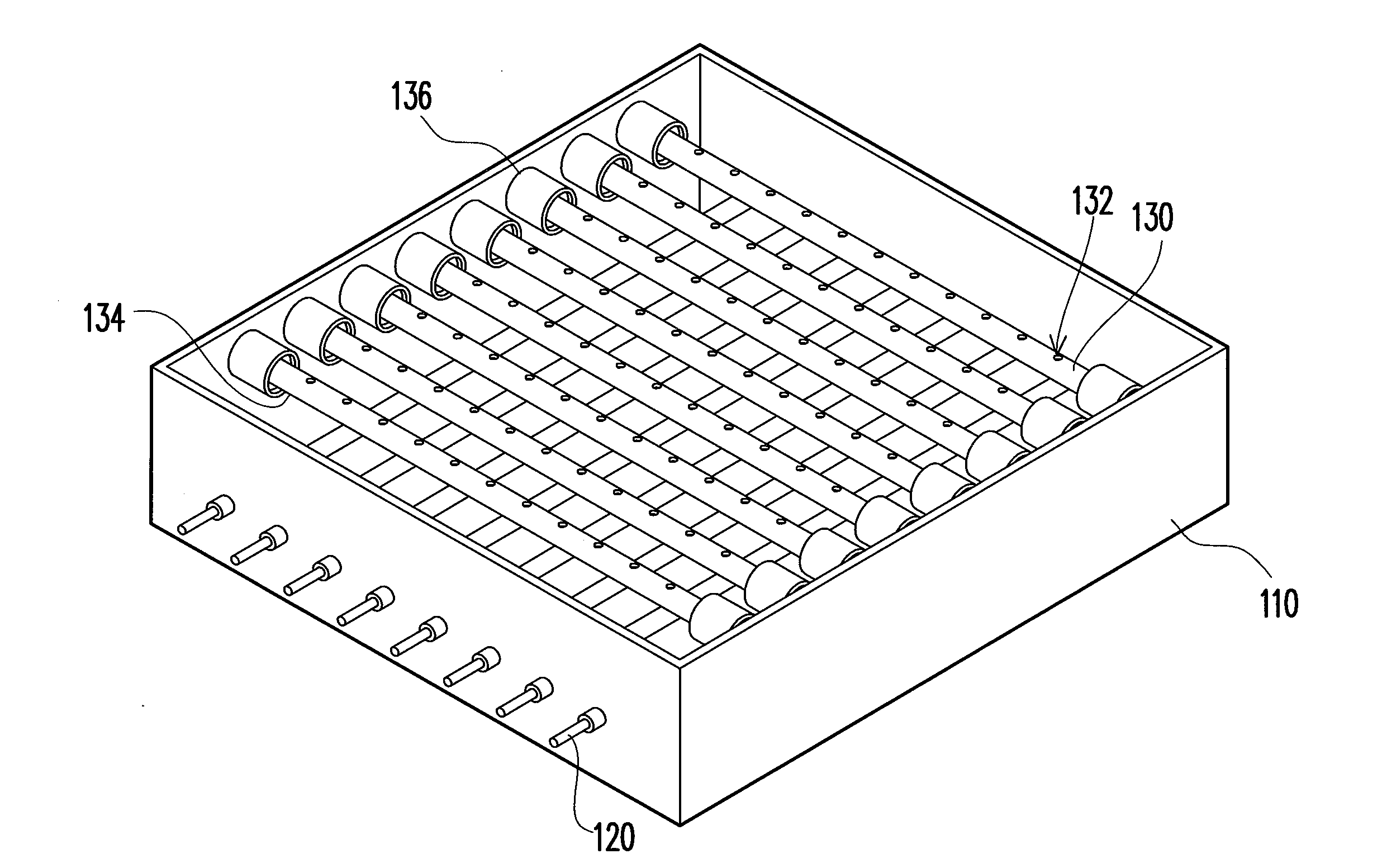
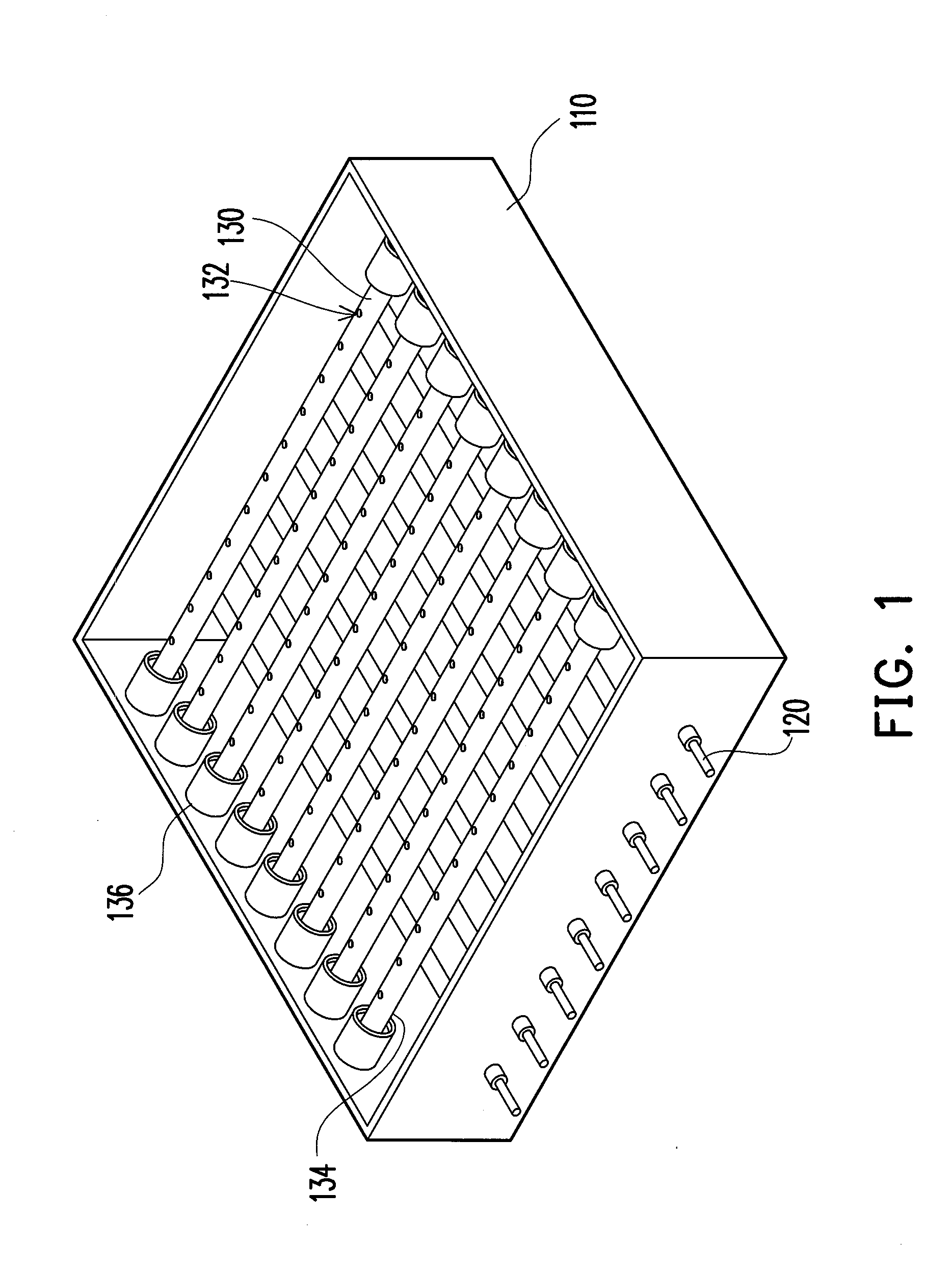
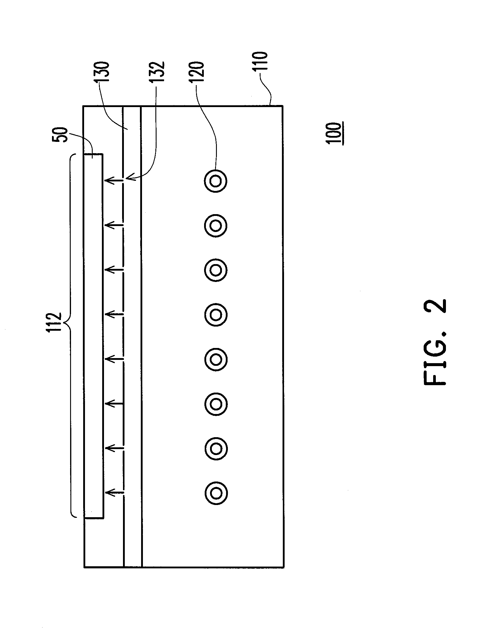
[0020]FIG. 1 is a partial three-dimensional view of a plasma apparatus according to an exemplary embodiment of the disclosure, and FIG. 2 is a cross-sectional view of the plasma apparatus according to an exemplary embodiment of the disclosure. Referring to FIG. 1 and FIG. 2, the plasma apparatus 100 includes a chamber 110, an electrode set 120 and a gas supplying tube set 130. The chamber 110 has a supporting table 112 for supporting a substrate 50. The gas supplying tube set 130 is located between the supporting table 112 and the electrode set 120. The gas supplying tube set 130 is disposed in the chamber 110 and has a plurality of gas apertures 132, where the gas apertures 132 are perpendicular to an axial direction of the gas supplying tube set 130, and the gas apertures 132 can be disposed in different rotation angles relative to the axial direction. Namely, in the present exemplary embodiment, the gas apertures 132 face to the supporting table 112, though in other embodiments, ...


PUM

PropertyMeasurementUnit
Dielectric polarization enthalpyaaaaaaaaaa
Angleaaaaaaaaaa
Shapeaaaaaaaaaa

Abstract

A plasma apparatus including a chamber, an electrode set and a gas supplying tube set is provided. The chamber has a supporting table for supporting a substrate. The gas supplying tube set is disposed in the chamber and has a plurality of gas apertures. The gas supplying tube set is located between the supporting table and the electrode set.

Description

CROSS-REFERENCE TO RELATED APPLICATION[0001]This application claims the priority benefit of Taiwan application serial no. 99143078, filed on Dec. 9, 2010. The entirety of the above-mentioned patent application is hereby incorporated by reference herein and made a part of this specification.BACKGROUND[0002]1. Field of the Disclosure[0003]The disclosure relates to a plasma apparatus. Particularly, the disclosure relates to an inductively coupled plasma (ICP) apparatus.[0004]2. Description of Related Art[0005]Plasma is ionised gas containing ions or electrodes and radicals, which has a wide application. Plasma treatment refers to that the gas is transformed to the plasma, and the plasma gas is deposited on a substrate, or the plasma gas is used for cleaning, coating, sputtering, plasma chemical vapor deposition, ion implantation, ashing or etching, etc. During operation of a commonly used plasma treatment apparatus, after a powerful electric filed is formed between two electrodes, the ...

Claims


Application Information

Patent Timeline
IPC IPC(8): C23F1/08H05H1/24
CPCH01J37/32532H01J37/32449
Inventor CHEN, HUI-TACHANG, CHUN-HAOLIN, TUNG-YINGKO, MING-HSIEN
Owner IND TECH RES INST
Why Eureka
Try Eureka