Method for recycling deoiled water using counterflow falling-film evaporators

Active Publication Date: 2012-06-14
AQUATECH INT LLC
View PDF5 Cites 40 Cited by
  • Summary
  • Abstract
  • Description
  • Claims
  • Application Information

AI Technical Summary

Benefits of technology

[0024]The provision of large evaporator sump volume such as that provided in the technology currently used for these applications would provide residence time for silicate precipitation and would increase rates of silica scaling.
[0025]Embodiments of the invention also reduce the chemical consumption requirement of the strong base, since the evaporator can operate at lower pH than would otherwise be required to ensure total silica solubility in an evaporator with a very long residence time (i.e. large sump).
[0026]This counterflow VTFF evaporator technology also has the advantage of providing a minimal total installed cost (TIC) relative to the conventional technology currently applied (co-current falling-film evaporation). Since the counterflow evaporator is designed to operate at above-neutral pH, the materials of construction for most applications can be low-alloy austenitic or duplex stainless steels, which is a substantially lower cost compared to the materials (such as 6% Molybdenum Stainless Steel) that would be required by a co-current evaporator technology op

Problems solved by technology

Since the hardness is removed from solution, it is not dissolved or

Method used


Image

  • Method for recycling deoiled water using counterflow falling-film evaporators
  • Method for recycling deoiled water using counterflow falling-film evaporators
  • Method for recycling deoiled water using counterflow falling-film evaporators

Examples


example

[0055]Embodiments and aspects of the invention may be further understood by reference to the example below. The example should be understood to show exemplary aspects of the invention, but should not be construed to limit the claims.

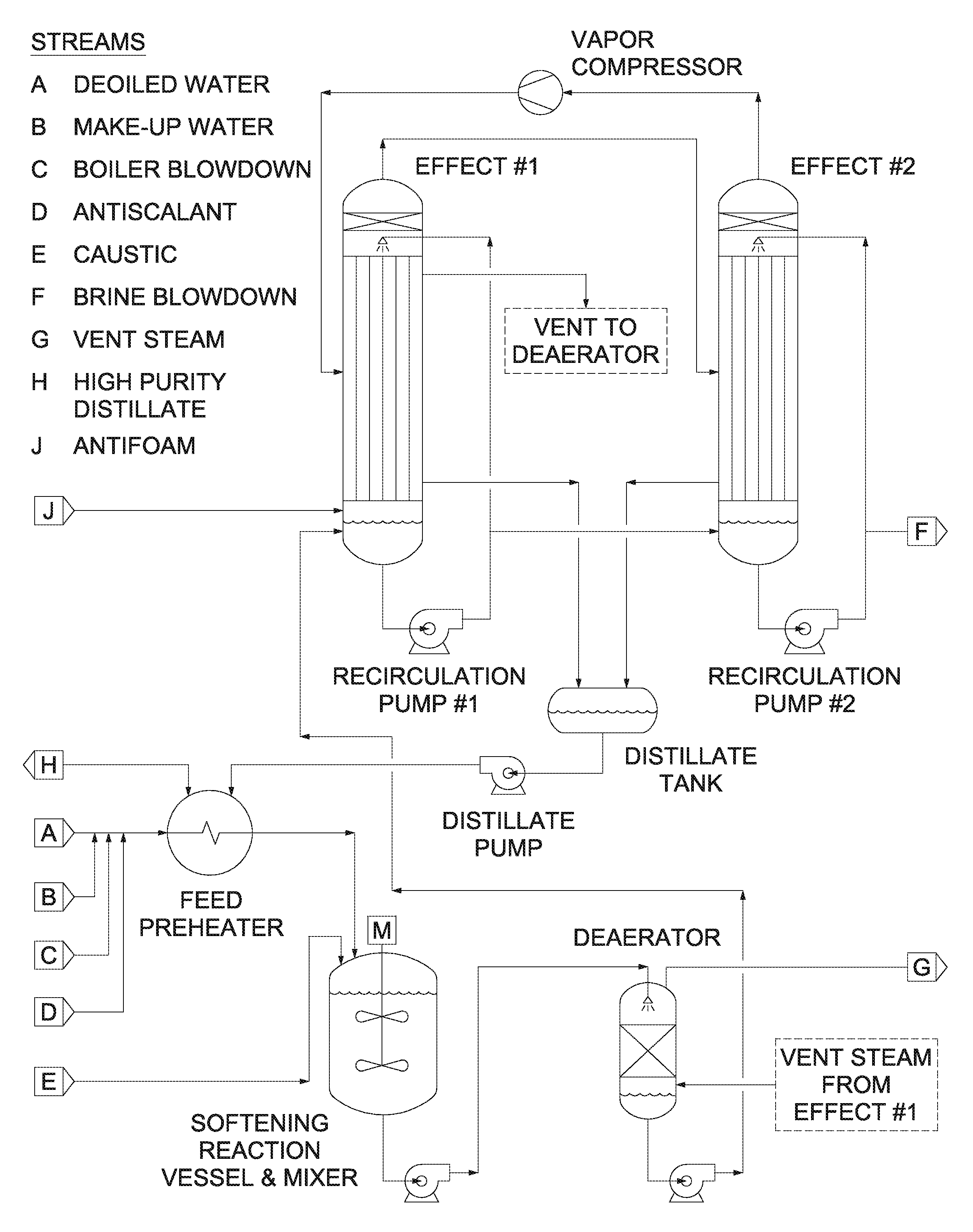
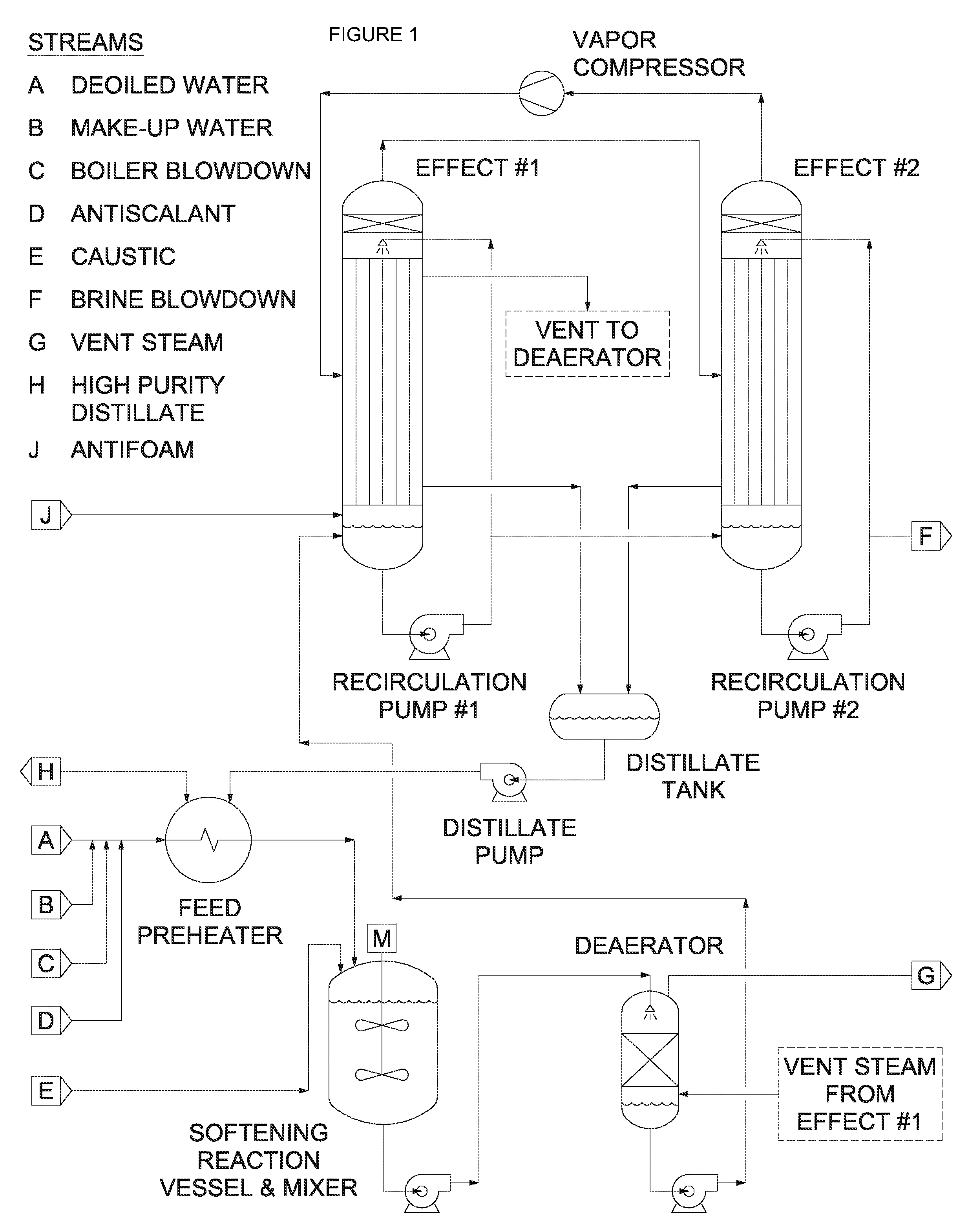
[0056]For the purposes of this example, assume a 5,000 bpd SAGD oil production facility having a continuous boiler feedwater requirement of 273 m3 / h. The high pressure drum boiler produces steam for injection into the underground formation. An oil and water mixture is pumped to the surface through the producing well. The oil is separated and removed as product. The separated water receives further treatment for oil removal to the order of 3 / h and that the evaporator system concentrates this stream approximately 20 times to produce a high-purity distillate stream of 273 m3 / h (equal to the boiler feedwater requirement) and a brine blowdown stream of 14 m3 / h.

[0057]Consider a conventional evaporator system that is designed with the process as described in th...


PUM

PropertyMeasurementUnit
Volumeaaaaaaaaaa
Volumeaaaaaaaaaa
Volumeaaaaaaaaaa

Abstract

We provide an evaporator technology for treatment of produced water that may be deoiled water. Systems described herein utilize a vertical tube heat exchanger bundle where the brine is distributed in a falling film along the inside of the tube wall. Condensing steam causes a portion of the deoiled water to evaporate; this water vapor travels upward in a counterflow direction relative to the deoiled water. This evaporator technology provides several design advantages over the conventional vertical tube co-current flow evaporators (where the vapor flows downward with the falling film). These advantages include a minimal total installed cost (TIC) as well as offering optimal design features for water chemistry management.

Description

CROSS-REFERENCE TO RELATED APPLICATIONS[0001]This application claims priority to U.S. Provisional Patent Application No. 61 / 422,965, filed on Dec. 14, 2010. That application is incorporated by reference herein.BACKGROUND OF THE INVENTION[0002]1. Field of the Invention[0003]Embodiments of the invention relate to methods, systems, and apparatus for recycling deoiled water for heavy oil production.[0004]2. Background of the Related Art[0005]Oil may be extracted from underground reserves using a number of processes. One of those processes is steam-assisted gravity drainage (SAGD). In a typical SAGD process, steam is used for downhole injection to increase the flowability of oil and allow it to be withdrawn from a formation. This process generates a large volume of water that includes oil and other contaminants that flows to the surface through a producing well. It is important for the process to recycle this water for two primary reasons.[0006]First, the boiler that produces the steam f...

Claims


Application Information

Patent Timeline
IPC IPC(8): E21B43/40C02F9/00E21B43/34B01D1/22
CPCB01D1/065B01D1/28B01D5/006C02F2101/32C02F1/20C02F1/40C02F1/048
Inventor BJORKLUND, DANIEL P.KERSEY, DAVIDMANDIGO, GREGORY J.TIWARI, CHANDRAKANT
Owner AQUATECH INT LLC
Why Eureka
Try Eureka