Projection display apparatus

a technology of projection display and display device, which is applied in the direction of projectors, color television details, instruments, etc., can solve the problems of reliability, increase the size of the device, and degrade the quality of the projected image, and achieve the effect of stably reducing the noise of speckles

Inactive Publication Date: 2012-06-14
ASAHI GLASS CO LTD
View PDF13 Cites 20 Cited by
  • Summary
  • Abstract
  • Description
  • Claims
  • Application Information

AI Technical Summary

Benefits of technology

[0026]The present invention provides a projection display device exhibiting an effect to stably reduce speckle noise simply in the case where a light source with coherence is used.

Problems solved by technology

In a projection display device using a laser as a light source, however, granularity speckle noise derived from the coherence of laser is caused in a projected image, resulting in a problem that the quality of the projected image is degraded.
In the structure of the non-speckle display device of JP-A-H06-208089, however, a driver device including a motor or a coil is necessary for rotating or vibrating the diffuser element, which not only increases the size of the device but also causes a problem of reliability due to occurrence of noise through the mechanical vibration.
Furthermore, there arises another problem that a response speed is lowered as the thickness of the liquid crystal film is increased.
Furthermore, there is a problem that a response speed sufficient for modulating the phase at a higher speed than a visually recognizable speed may not be attained by using the nematic liquid crystal.
In addition, since inorganic crystal is used, there arises another problem of difficulty in fabrication through processing or the like.

Method used


Image

  • Projection display apparatus
  • Projection display apparatus
  • Projection display apparatus

Examples


embodiment 1

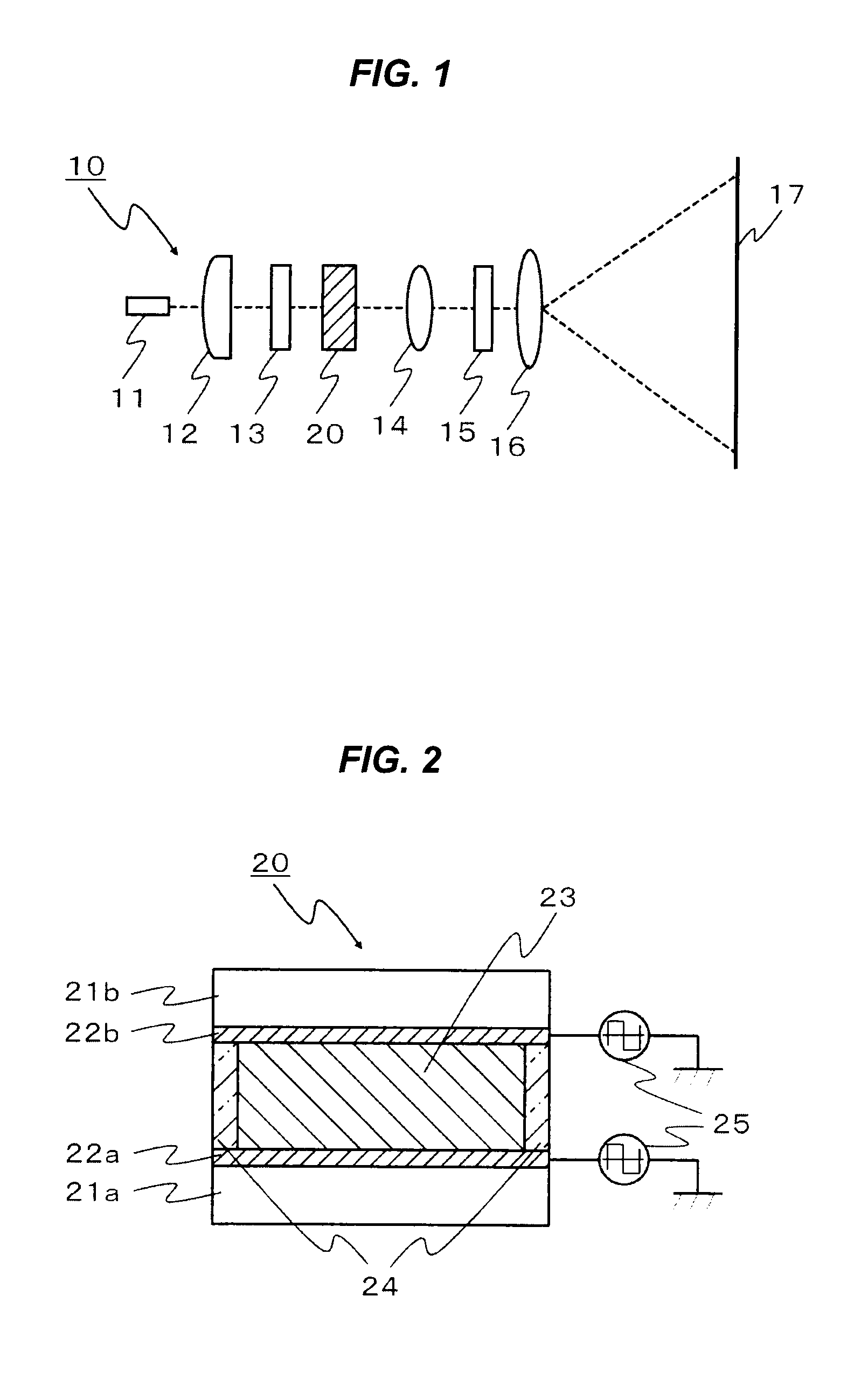
[0033]FIG. 1 is a schematic diagram illustrating an example of the structure of a projection display device 10 according to this embodiment. Light emitted from at least one laser 11, such as a semiconductor laser or a solid state laser, used as a light source for emitting light with coherence (hereinafter referred to as “coherent light”) corresponding to light emitting means is condensed by a collimator lens 12 into substantially parallel lights before passing through a polarizer 13. It is noted that a light source including at least one laser is designated as a light source unit as a whole. When, for example, a semiconductor laser is used as the laser 11, it emits linear polarized light and the polarization direction may be varied or changed with time due to fabrication variation or temperature change in use environment. The polarizer 13 is used for making such a polarization state of the light constant.

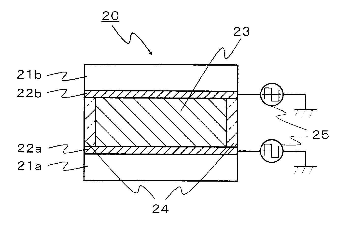
[0034]The light having passed through the polarizer 13 is temporally changed by...

embodiment 2

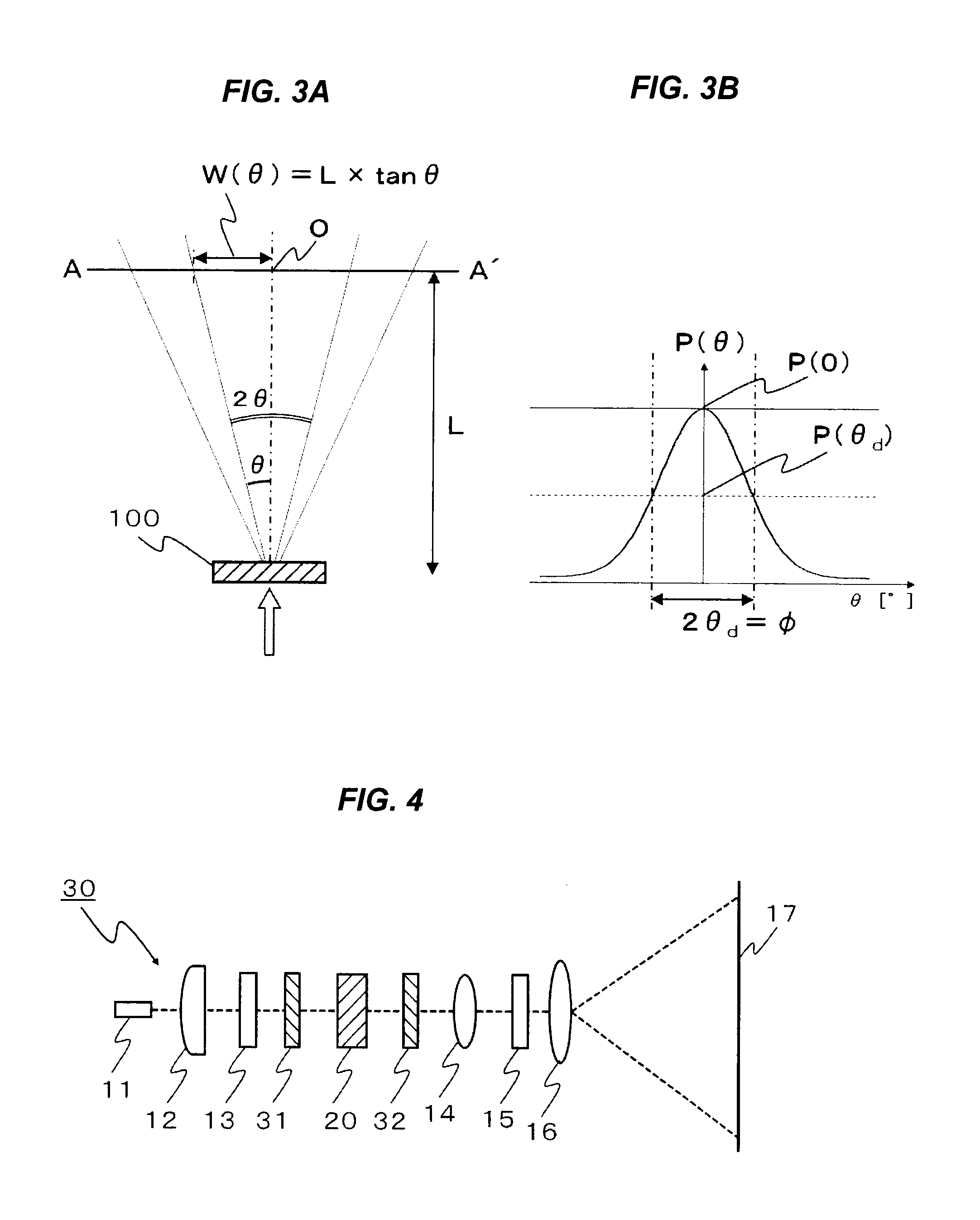
[0075]FIG. 4 is a schematic diagram illustrating the structure of a projection display device 30 according to this embodiment, in which like reference numerals are used to refer to like optical elements and the like used in the projection display device 10 so as to avoid repetition of the description. The projection display device 30 includes, in the optical path between the laser 11 corresponding to the light source and the screen 17 for displaying an image thereon, a light scattering element 31 disposed in an optical path between the polarizer 13 and the liquid crystal element 20 and a light scattering element 32 disposed in an optical path between the liquid crystal element 20 and the focusing lens 14. Both of the light scattering elements 31 and 32 may be provided, merely one of the light scattering elements 31 and 32 may be provided, or one or both of the light scattering elements 31 and 32 may be stacked on the liquid crystal element 20.

[0076]Each of the light scattering eleme...

embodiment 3

[0077]FIG. 5 is a schematic diagram illustrating the structure of a projection display device 40 according to this embodiment, in which like reference numerals are used to refer to like optical elements and the like used in the projection display device 30 so as to avoid repetition of the description. The projection display device 40 includes, in an optical path between the focusing lens 14 and the spatial light modulator 15, light homogenizing means 41 so that the light having been temporally modulated in the phase and / or polarization by passing through the liquid crystal element 20 may irradiate a region for forming an image in the spatial light modulator 15 with homogenous light intensity. Although the projection display device 40 includes the light scattering elements 31 and 32, these elements may be omitted as in the projection display device 10 of Embodiment 1.

[0078]The light homogenizing means 41 may be a combination of a rod integrator 42 and a focusing lens 43. For example,...


PUM

PropertyMeasurementUnit
frequencyaaaaaaaaaa
red wavelengthaaaaaaaaaa
acceptance angleaaaaaaaaaa

Abstract

A projection display device includes: a light source unit including at least one light source configured to emit coherent light; an image light generation unit configured to generate an image light by modulating light emitted by the light source unit; a projection unit configured to project the image light; and a liquid crystal element, disposed in an optical path between the light source unit and the image light generation unit, configured to temporally change a phase and/or polarization of transmitted light, wherein: the liquid crystal element at least includes transparent electrodes respectively provided on opposing faces of a plurality of transparent substrates; a liquid crystal layer including smectic phase liquid crystal showing spontaneous polarization under voltage application is sandwiched between the transparent electrodes; and an AC voltage is applied to the liquid crystal layer through the transparent electrodes.

Description

BACKGROUND[0001]1. Field of the Invention[0002]The present invention relates to a projection display device, and more particularly, it relates to a projection display device using a light source with coherence.[0003]2. Description of the Related Art[0004]As a light source for a display device that displays a projected image on a screen such as a data projector or a rear-projection television, a ultra-high pressure (UHP) mercury lamp has been conventionally used, and use of a laser has been proposed from the viewpoint of the lifetime of the light source. Furthermore, since the UHP lamp has a spectrum with a broad wavelength band in the vicinity of 645 nm, that is, a red wavelength region, owing to its characteristics, a combined light source using a laser as a red light source and UHP lamps for blue and green wavelength regions has been also proposed.[0005]In a projection display device using a laser as a light source, however, granularity speckle noise derived from the coherence of ...

Claims


Application Information

Patent Timeline
Patent Type & Authority Applications(United States)
IPC IPC(8): G02F1/1335
CPCG02F1/13G02B26/06G02B27/286G02F1/141G03B21/2033H04N9/3161G02F2001/0139G02B27/48G02F1/0139
Inventor KOYANAGI, ATSUSHIKONISHI, TEPPEIKUMAI, HIROSHI
Owner ASAHI GLASS CO LTD
Why Eureka
Try Eureka