Wind noise detection method and system

a detection method and wind noise technology, applied in the direction of transducer details, electrical transducers, electrical apparatus, etc., can solve the problems of difficult detection of wind noise signals from two or more microphone signals, etc., and achieve the effect of reducing power consumption and saving computational resources

Active Publication Date: 2012-06-14
INVENSENSE
View PDF5 Cites 85 Cited by
  • Summary
  • Abstract
  • Description
  • Claims
  • Application Information

AI Technical Summary

Benefits of technology

[0027]The multi-microphone system may comprise a sample rate converter operatively interconnected in-between the first and second digital microphone signals and the signal processor assembly. The sample rate converter is adapted to down-sample the first and second digital microphone signals to a lower sampling frequency than the predetermined sampling frequency—for example by dividing the predetermined sampling frequency with an integer number such as 2, 4, 8 etc. This embodiment is highly useful in situations where the wind noise detection can be performed at a much lower sampling rate or frequency than the predetermined sampling frequency. Detecting wind noise at the lower sampling frequency leads to substantial savings in computational resources imparted to the signal processor assembly and thus to a corresponding reduction of power consumption.

Problems solved by technology

Making a reliable detection of wind noise signals has, however, proven to be difficult for example due to overlapping spectral or temporal content of the wind noise signals and desired signals such as musical and speech signals.
In multi-microphone systems it has been difficult to detect wind noise from two or more microphone signals due to a mismatch between sensitivity and frequency responses of two microphones.

Method used


Image

  • Wind noise detection method and system
  • Wind noise detection method and system
  • Wind noise detection method and system

Examples


first embodiment

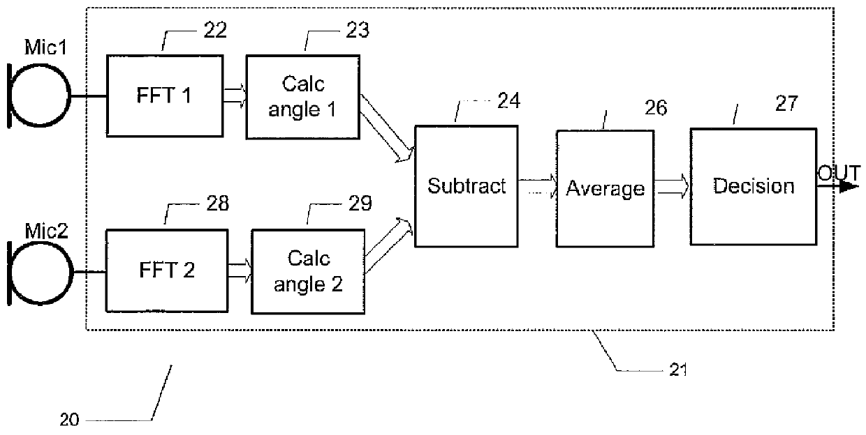
[0060]FIG. 1 a schematic drawing of a multi-microphone system 1 according to the present invention comprising a first microphone, Mic 1, and a second microphone, indicated as Mic 2, operatively coupled to a signal processor assembly 11 so as to supply first and second microphone signals thereto. The first and second microphone signals are preferably provided in digital form to the signal processor assembly 11, but ND converters have been left out of the drawing for simplicity. In practice, each microphone, Mic 1 and Mic 2, may comprise an integral A / D converter so as to supply a digital microphone signal at a predetermined sampling frequency. Alternatively, the signal processor assembly 11 may comprise a pair of suitable A / D converters, or a single multiplexed A / D converter, coupled to receive the first and second microphone signals in analog form and convert these to digital form before routing to the signal processor assembly 11.

[0061]The signal processor assembly 11 comprises fir...

second embodiment

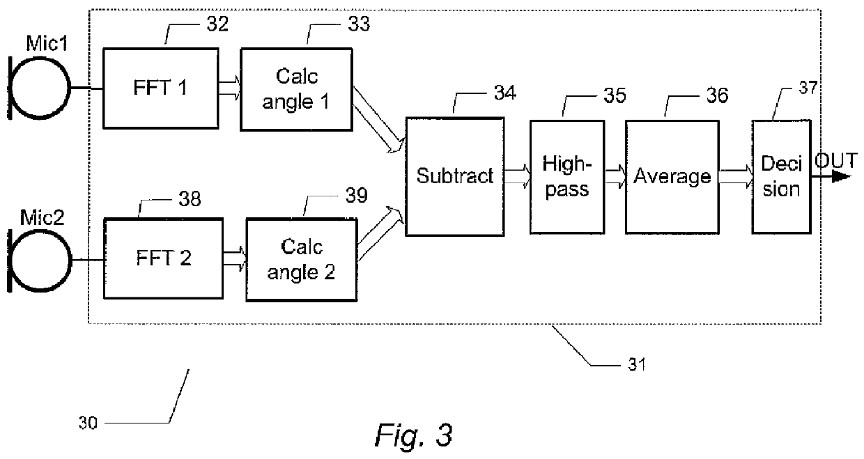
[0072]FIG. 3 is a schematic drawing of a multi-microphone system 30 according to a third and preferred embodiment of the present invention. Compared to the multi-microphone system 20 described above in connection with FIG. 2, the present multi-microphone system 30 comprises a high-pass filter 35 operatively coupled in-between a subtraction function 34 and an averaging function 36 within the signal processor assembly 31. Functions and features in the present embodiment of the invention are substantially identical to the correspondingly marked functions and features in the invention and will therefore not be described in more detail than necessary.

[0073]Another difference between the present embodiment and the previously-described first and second embodiments of the invention is that the phase angle differences between the first and second microphone signals are determined separately in three different sub-bands in the present multi-microphone system compared to the single sub-band, F...


PUM


Abstract

The present invention relates to a multi-microphone system and method adapted to determine phase angle differences between a first microphone and a second microphone signal to detect presence of wind noise.

Description

[0001]The present invention relates to a multi-microphone system and method adapted to determine phase angle differences between first microphone and second microphone signals to detect presence of wind noise.BACKGROUND OF THE INVENTION[0002]Wind induced noise signals or wind noise presents a significant problem to sound reception in a diverse range of portable electronic equipment for outdoors use such as mobile terminals, hearing instruments, headsets, sound recording cameras etc. Wind noise is often annoying during a conversation where it can lower intelligibility of desired speech signals by auditory masking of important speech cues and during sound recordings where wind noise corrupts fidelity of music recordings.[0003]Wind noise is caused by turbulent airflow around surface features proximate to microphone inlet ports of the portable electronic equipment. These surface features convert a steady flow of wind into turbulent pressure fluctuations which are picked up by the microp...

Claims


Application Information

Patent Timeline
Patent Type & Authority Applications(United States)
IPC IPC(8): H04R3/00
CPCH04R2410/07H04R3/005
Inventor PETERSEN, KIM SPETZLERSPOLTZ, THOMAS KROGHTHOMSEN, HENRIK
Owner INVENSENSE
Why Eureka
Try Eureka