Clamp structure

a technology of clamshell and conductive ribbon, which is applied in the direction of snap fasteners, heat collector mounting/support, manufacturing tools, etc., can solve the problems of affecting power transmission, affecting the stability of connection between the conductive ribbon and the junction box, and it takes at least half a day to cure the solar panel. , to achieve the effect of convenient installation or removal, enhanced stability of connection between the junction box and the solar panel, and increased yield ra

Active Publication Date: 2012-06-21
KS TERMINALS INC
View PDF5 Cites 9 Cited by
  • Summary
  • Abstract
  • Description
  • Claims
  • Application Information

AI Technical Summary

Benefits of technology

[0009]The primary objective of the present invention is to provide the foregoing clamp structure, wherein each second jaw forms the first arc near the second jaw opening and the second arc away from the base plate, the first arc having a greater curvature than the second arc. The curvatures of the first arc and the second arc of each second jaw are so designed that, when a junction box and a solar panel that are bonded together enter the interior of the clamp structure from the first jaw opening through the gap between the first jaws, the second jaws are guided into secure engagement with recesses of the junction box, thereby fixing the junction box laterally in position. Consequently, both the junction box and the solar panel are prevented from being shifted by an external force during the bonding process, and the stability of connection between the junction box and the solar panel is enhanced, which helps increase the yield rate of the solar panel.
[0010]Another objective of the present invention is to provide the foregoing clamp structure wherein, with each second jaw forming the first arc near the second jaw opening and the second arc away from the base plate, and with the first arc having a greater curvature than the second arc, the second jaws each have a hook-shaped configuration that is formed by the first and the second arcs. The hook-shaped configuration allows the second jaws to be easily guided into or out of secure engagement with the recesses of the junction box. Thus, not only can the clamp structure be conveniently installed or removed, but also the risk of junction box damage is reduced.
[0011]An additional objective of the present invention is to provide the foregoing clamp structure wherein, with each second jaw forming the first arc near the second jaw opening and the second arc away from the base plate, and with the first arc having a greater curvature than the second

Problems solved by technology

However, the silicone used to bond the junction box and the solar panel takes at least half a day to a day to become completely cured.
The shifting may cause the connection between the conductive ribbon and the junction box to loosen, wh

Method used


Image

  • Clamp structure
  • Clamp structure
  • Clamp structure

Examples


Embodiment Construction

[0016]The present invention discloses a clamp structure wherein the clamping method employed is understandable to people of ordinary skill in the art and therefore is not described in detail herein. Also, the drawings referred to in the following description only schematically depict structures related to the technical features of the present invention and hence are not, and need not be, drawn to scale.

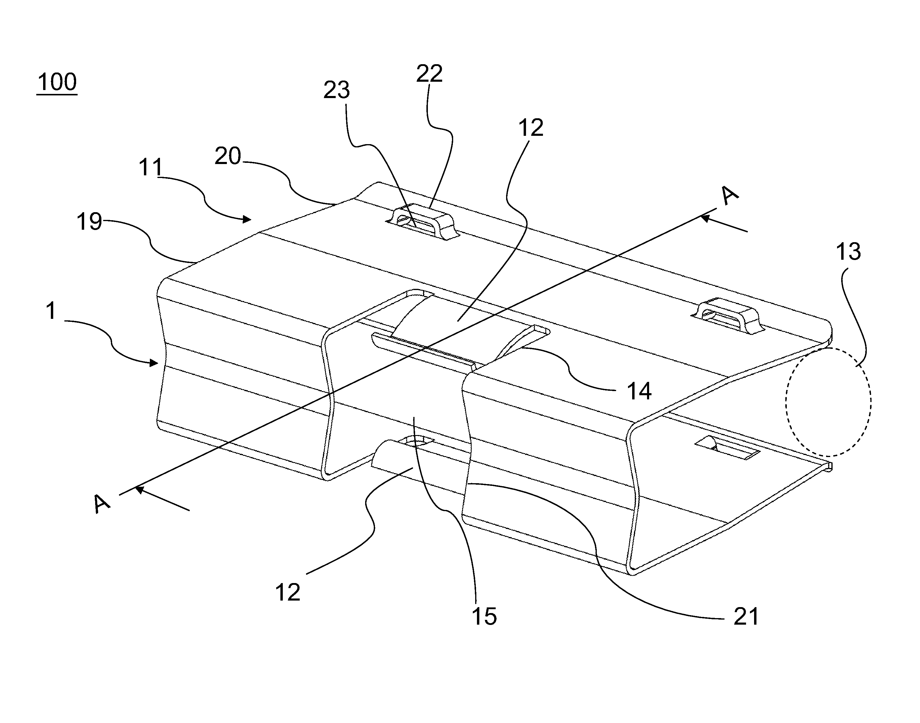
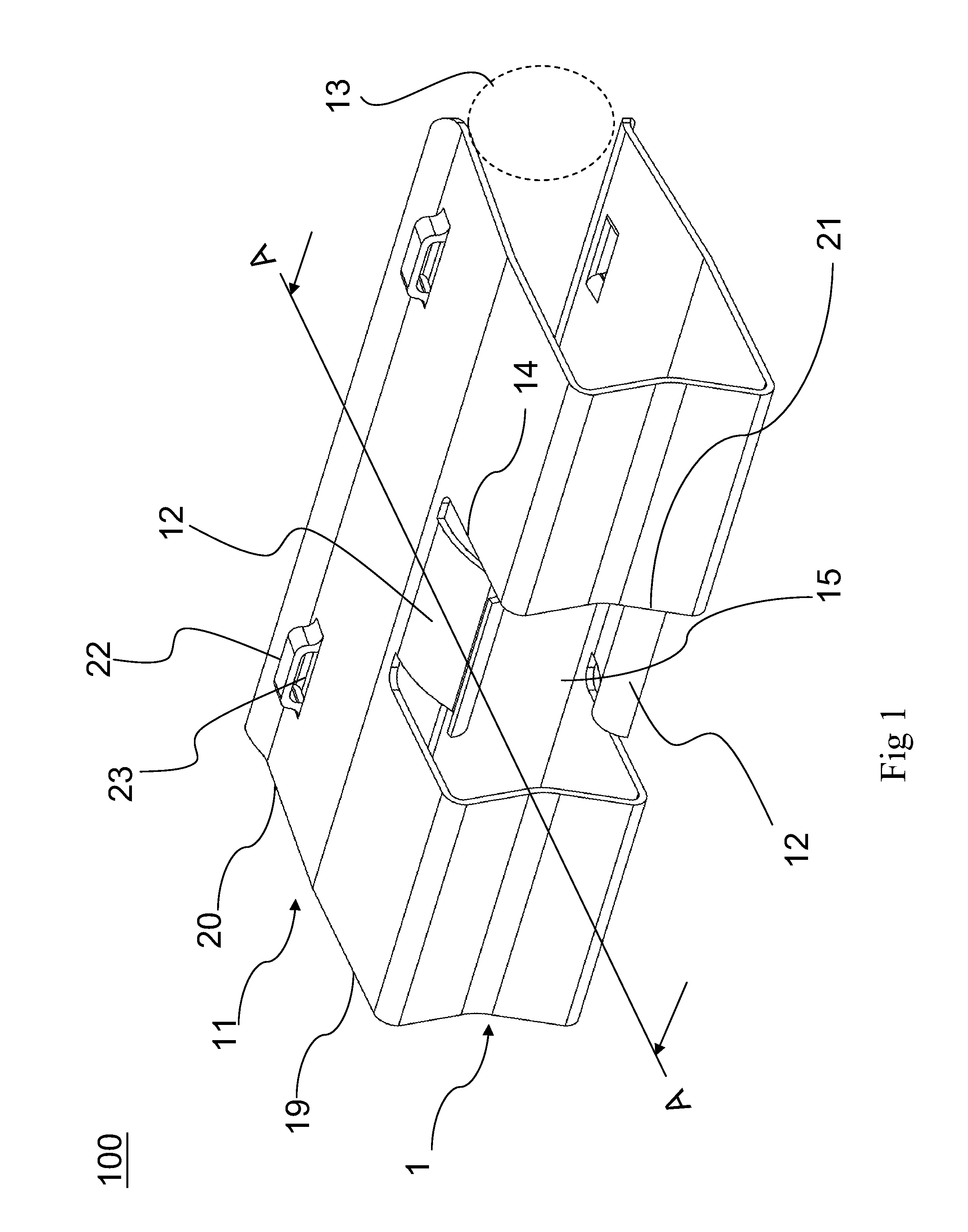
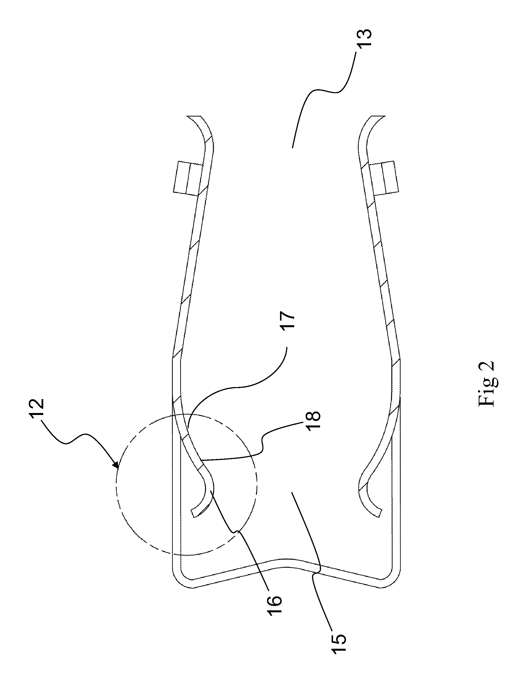
[0017]Referring to FIGS. 1 and 2, a clamp structure 100 in accordance with the first preferred embodiment of the present invention includes a base plate 1, a pair of first jaws 11, and a pair of second jaws 12. The pair of first jaws 11 extend from two sides of the base plate 1 respectively in a face-to-face manner such that the ends of the first jaws 11 form a first jaw opening 13. Also, the pair of first jaws 11 are formed with a pair of cutouts 14 in a face-to-face manner. The second jaws 12 stem from the pair of cutouts 14 respectively and extend towards the base plate 1; as a res...


PUM


Abstract

A clamp structure includes a base plate, a pair of first jaws, and a pair of second jaws. The first jaws extend respectively from two sides of the base plate in a face-to-face manner and form a first jaw opening at their ends. The first jaws are also formed with a pair of cutouts that face each other. The second jaws extend respectively from the pair of cutouts towards the base plate and form a second jaw opening at their ends. Each second jaw has a hook-shaped configuration composed of a first arc near the second jaw opening and a second arc away from the base plate, wherein the first arc has a greater curvature than the second arc. A junction box and a solar panel which are bonded together can be inserted into and thus clamped by the clamp structure so as to be secured against lateral shifting.

Description

BACKGROUND OF THE INVENTION[0001]1. Technical Field[0002]The present invention relates to a clamp structure and, in particular, to a clamp structure used in a solar cell.[0003]2. Description of Related Art[0004]With an increasing shortage of modern energy, the development of new energy sources—such as the solar cell—has drawn great attention from the international community. The solar cell has a plurality of advantages such as environmental friendliness, energy saving, and a wide application range. Also, the solar cell technology is currently more mature than any other alternative energy technologies. Nowadays, the improvement of solar cell performance has become a common goal in the industry. In order to achieve that goal, it is important to draw electricity out of the solar cell efficiently. In general, the electricity generated by a solar cell is led out of the solar cell by a conductive ribbon, and a junction box is usually used to keep the conductive ribbon firmly connected to ...

Claims


Application Information

Patent Timeline
IPC IPC(8): F16B2/06
CPCB25B5/06F16B2/245F24J2002/4663Y10T24/44017Y10T24/44923Y10T24/344Y10T24/44778H02S40/34F24S2025/6003Y02E10/50
Inventor LIN, CHIH-HSIN
Owner KS TERMINALS INC
Why Eureka
Try Eureka