Die stamper assembly, injection compression moulding apparatus and method of manufacturing optical data carriers

a technology of injection compression moulding and die-cutting, which is applied in the direction of dough shaping, manufacturing tools, applications, etc., can solve the problems of affecting the flatness of the central data part of the stamper, the quality of the moulded first disc part does not always meet the specifications, and the location of unwanted deformations in the vacuum channel aperture, etc., to achieve the effect of improving the injection moulding process, affecting the flatness of the central data part, and moving more easily

Inactive Publication Date: 2012-06-21
AXXICON MOULDS EINDHOVEN BV +1
View PDF6 Cites 0 Cited by
  • Summary
  • Abstract
  • Description
  • Claims
  • Application Information

AI Technical Summary

Benefits of technology

[0012]The invention is based on the insight that by introducing the venting holder, positioned between the venting ring and the first die part, for holding the circumference of the first stamper, the gap between the first stamper and the venting ring can be reduced to zero or to a sufficient small dimension in order to prevent leakage of the plastic material during compression, while allowing venting of air escaping from the mould cavity and allowing that the venting ring is able to move more easily with respect the first die part when the second die part is moving to the first die part during compression. Hence the injection moulding process is improved.
[0013]Furthermore, in this configuration, because the venting holder can hold the first stamper on the first die part, the apertures of the vacuum channels in the data part of the first die part can be omitted. During compression the pressure in the mould cavity, which is about 600 bar, exerts a force on the first stamper. This force causes the unwanted deformations at the locations of the apertures of the vacuum channels and affects the flatness of the central data part of the stamper. The unwanted deformations are replicated to the first disc part and may contribute to a lower quality of the optical discs. By omitting the apertures in the central data part of the first die part the unwanted deformations in the flatness of the central data part of the first stamper are reduced and the quality of the first disc part, the optical disc and the injection moulding process is improved.

Problems solved by technology

During the injection compression moulding process a high pressure is generated inside the mould cavity which may cause the plastic material to leak through a gap between the side of the first stamper and the venting ring, which may cause that the venting ring, may not move or hardly move.
Furthermore, severe requirements are placed on the flatness and optical characteristics of the optical discs and it appears that the quality of the moulded first disc part does not always meet the specifications.
This force causes the unwanted deformations at the locations of the apertures of the vacuum channels and affects the flatness of the central data part of the stamper.

Method used


Image

  • Die stamper assembly, injection compression moulding apparatus and method of manufacturing optical data carriers
  • Die stamper assembly, injection compression moulding apparatus and method of manufacturing optical data carriers
  • Die stamper assembly, injection compression moulding apparatus and method of manufacturing optical data carriers

Examples


first embodiment

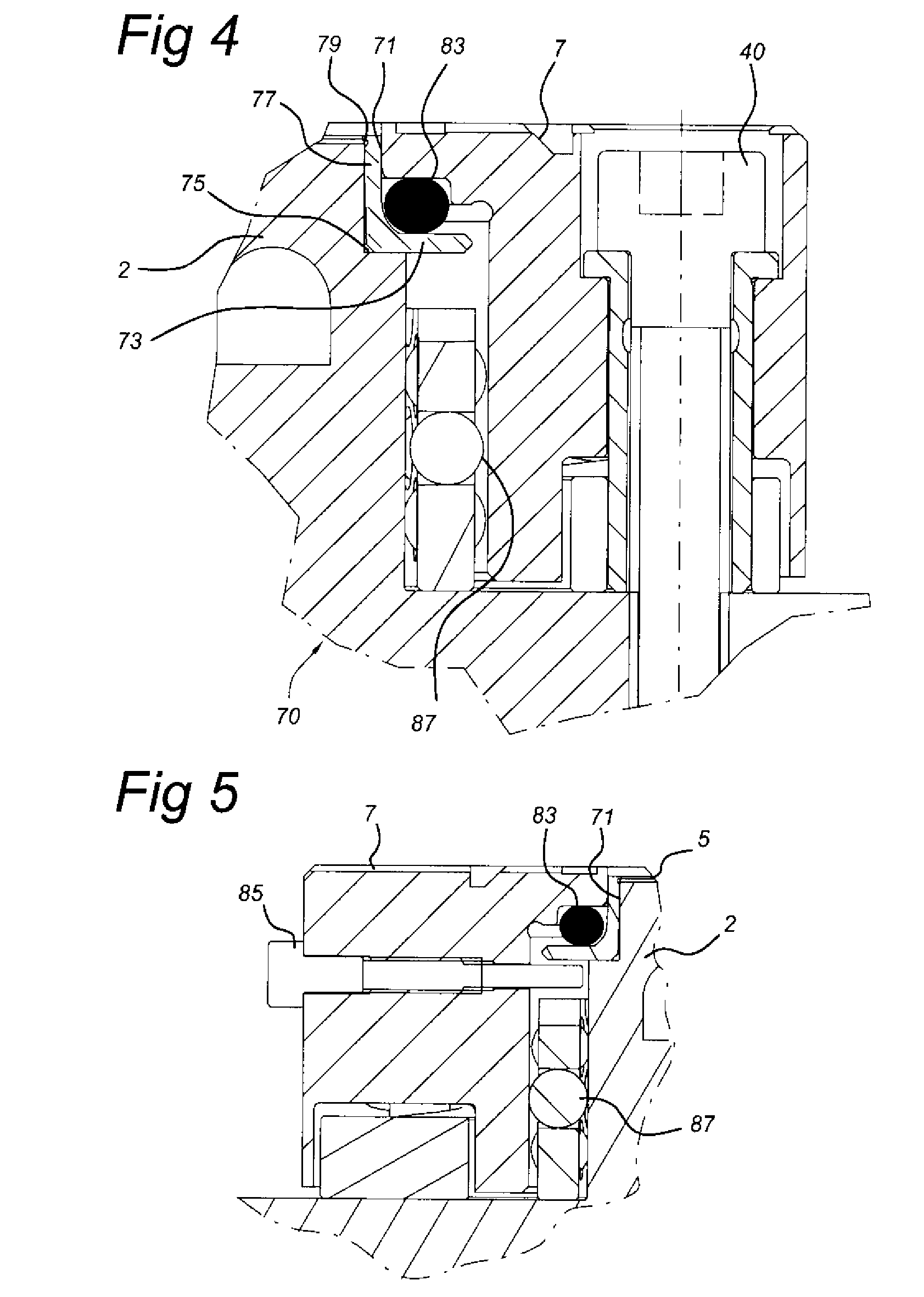
[0050]FIG. 4 shows a first detail IV of the cross section of the venting ring 7, the venting holder 71 and the first stamper 5 of FIG. 3. According to the invention the venting ring 7 is provided with the venting holder 71 for holding the circumferential side of the first stamper 5. The venting holder 71 comprises an angle cross section ring. A first leg 73 of the venting holder 71 is resting on a first flange 75 of the first die part 2. The inner side of a second leg 77 is provided with a recess 79 which allows thermal expansion of the first stamper 5. The thickness of the respective first leg 73 and the second leg 77 can be adapted to obtain a sufficient strength of the venting holder 71. Furthermore, the venting holder 71 defines a precise boundary of the first stamper 5 near an end of the pit spiral.

[0051]The venting holder 71 can be machined from a stainless steel mold steel which is manufactured via a powder metallurgy like processing technique. For example ELMAX®, as can be o...

second embodiment

[0059]FIG. 9 shows a top view of the die stamper 90, the venting ring 7, venting holder 71, the spring chambers 89 and the lifting bolts 85.

[0060]FIG. 10 shows a top view of a holder 100 and the venting ring 7.

[0061]FIG. 11 shows a side view of the holder 100 with provided with the bayonet catches 101, the venting ring 7, the bolts 40 and the lifting pins 85.

[0062]The holder 100 can be used for assembling and disassembling the venting ring 7 and the venting holder 71 from the first die part 2. The holder 100 is provided with bayonet catches 101 that cooperate with heads of the lifting bolts 85 of the venting ring 7.

[0063]For disassembling the die stamper assembly 1, and to remove the venting ring 7 and the venting holder 71 from the first die part 2, the first die part 2 is cooled down to about 90°. This is 10° C. below the standard operation temperature, which is about 100° C. When the lower temperature is reached, the operator can remove the venting ring 7 and the venting holder 7...


PUM

PropertyMeasurementUnit
pressureaaaaaaaaaa
thicknessaaaaaaaaaa
thicknessaaaaaaaaaa

Abstract

A die stamper assembly comprises a first die part for holding a first stamper and a second die part for mounting a second stamper, the die parts cooperating to define a mould cavity. The first stamper is mounted at a boundary of the first die part and the second stamper is mounted at a boundary of the second die part. The die stamper assembly further comprises a venting ring configured around and moveable with respect to the first die part and defining an outer boundary of the mould cavity. A venting holder arranged for holding the circumference of the first stamper and positioned between the first die part and the venting ring to attach the first stamper on the first die part allows venting of air escaping from the mould cavity and prevents leaking of plastic material out of the mould cavity.

Description

[0001]This application claims priority under 35 U.S.C. 119(a) to European Application No. 10195989.8, entitled “Die stamper assembly, injection compression moulding apparatus and method of manufacturing optical data carriers” filed Dec. 20, 2010, which is incorporated herein by reference.FIELD OF THE INVENTION[0002]The present invention is directed towards a die stamper assembly, an injection compression moulding apparatus and a method for manufacturing an optical data carrier.BACKGROUND OF THE INVENTION[0003]A die stamper assembly is used in an injection compression moulding apparatus for manufacturing of optical data carriers, for example a Digital Versatile Disc (DVD) optical disc, a Blu-ray (BD) optical disc, a combo DVD / BD optical disc or a multi-layer BD optical disc.[0004]The combo DVD / BD disc is a multi-layer optical disc according to the BD59 standard and can be played on a DVD player or a BD player. The combo DVD / BD disc comprises a first disc part and a second disc part. ...

Claims


Application Information

Patent Timeline
Patent Type & Authority Applications(United States)
IPC IPC(8): B29C45/03B29D11/00B29C45/17
CPCB29C45/263B29C2045/2653B29C2045/2648B29C45/34
Inventor VERHOEVEN, HENDRICUS JOHANNESVAN ASSELDONK, WILHELMUS GERARDUSKNIPS, PETER
Owner AXXICON MOULDS EINDHOVEN BV
Why Eureka
Try Eureka