

Quench tower catalyst recovery
a catalyst recovery and catalyst technology, applied in solvent extraction, liquid displacement, separation processes, etc., can solve the problems of maintenance and operation problems, incur significant expenses, etc., and achieve the effect of reducing the content of solid particles
- Summary
- Abstract
- Description
- Claims
- Application Information
AI Technical Summary
Benefits of technology
Problems solved by technology
Method used
Image

Examples
Embodiment Construction
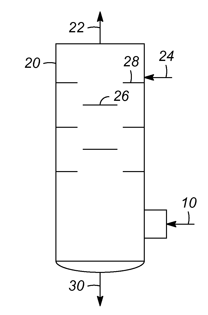
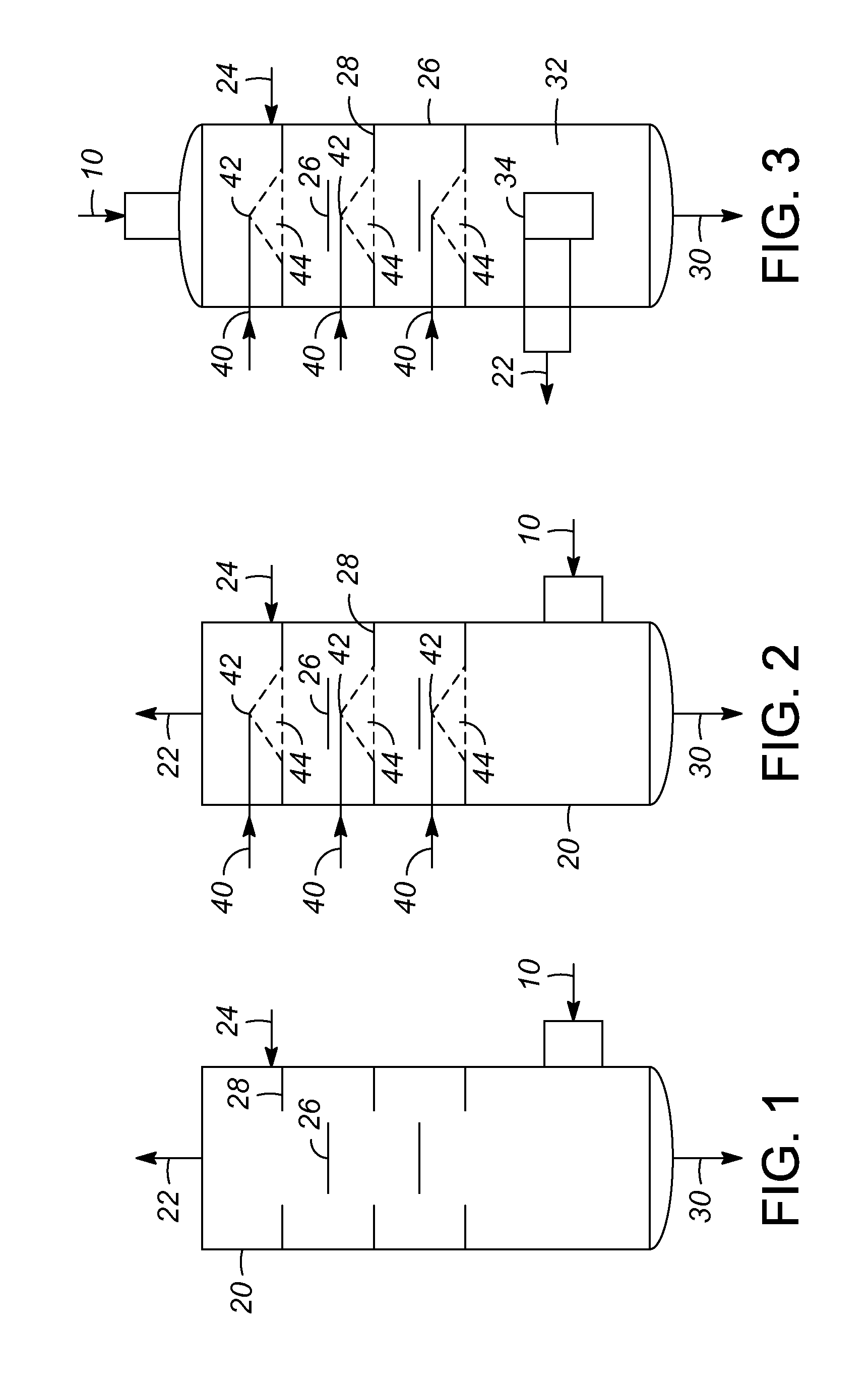
[0013]Many hydrocarbon processes involve the cooling and / or quenching of a product effluent stream. This can include the quenching of an intermediate process stream before the stream is passed to a subsequent process unit. One area where quenching is a factor in processing an effluent stream is the methanol to olefins (MTO) conversion process. The MTO process involves contacting a methanol feed stream with a catalyst in a reactor, thereby generating an effluent stream. The MTO reactor effluent contains catalyst fines and the current process includes a quench tower, as shown in FIG. 1. The process includes passing an effluent stream 10, comprising the reactor vapor to the quench tower 20, where the vapor flows up the tower 20 and through a vapor exit port 22. An aqueous quench stream 24 flows into the tower 20 and down over a series of disc 26 and donut 28 trays. The quench stream is intended to be captured catalyst fines in the bottom of the tower 20. The quench stream with fines 30...
PUM
| Property | Measurement | Unit |
|---|---|---|
| wetting capability | aaaaa | aaaaa |
| temperature | aaaaa | aaaaa |
| pressure | aaaaa | aaaaa |
Abstract
Description
Claims
Application Information