Induction motor, compressor and refrigerating cycle apparatus

a technology of compressor and compressor, which is applied in the direction of piston pumps, magnetic circuit rotating parts, and magnetic circuit shapes/forms/constructions, etc., can solve the problems of lowering the performance of the motor, and achieve the reduction of iron loss, increasing the width of the tooth of the rotor, and decreasing the width of the tooth of the stator

Active Publication Date: 2012-06-28
MITSUBISHI ELECTRIC CORP
View PDF2 Cites 18 Cited by
  • Summary
  • Abstract
  • Description
  • Claims
  • Application Information

AI Technical Summary

Benefits of technology

[0008]According to the induction motor of the present invention, by increasing the width of the tooth of the rotor and decreasing the width of the tooth of the stator, that is, by setting the core width of the rotor smaller than the core width of the stator as described above, an iron loss can be decreased thus improving the efficiency of the induction motor.

Problems solved by technology

However, in the induction motor disclosed in patent document 1, although efficiency of the motor can be improved by decreasing secondary resistance by making rotor slots formed in the rotor large, there has been a drawback that the enlargement of the opening of rotor slots generates the magnetic flux saturation of the rotor core thus lowering the performance of the motor.

Method used


Image

  • Induction motor, compressor and refrigerating cycle apparatus
  • Induction motor, compressor and refrigerating cycle apparatus
  • Induction motor, compressor and refrigerating cycle apparatus

Examples


embodiment 1

Induction Motor

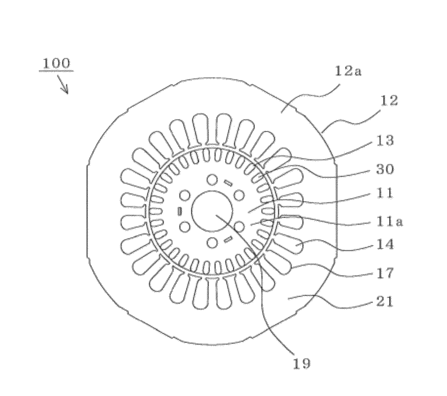
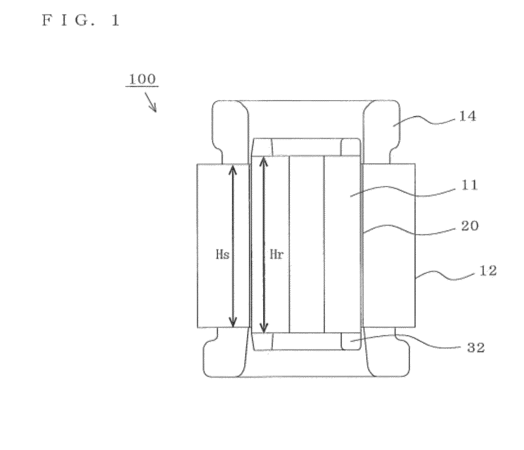
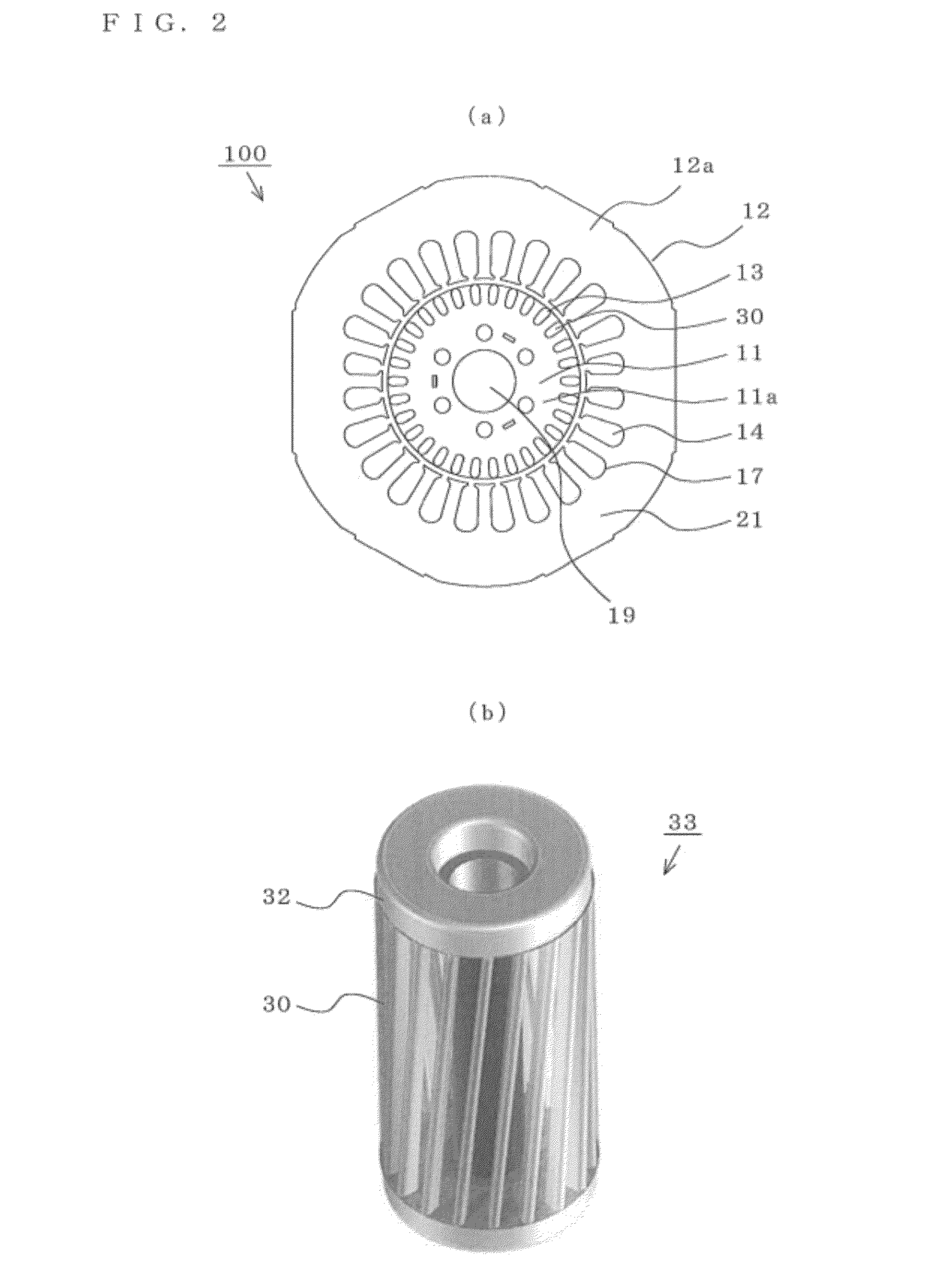
[0017]FIG. 1 to FIG. 3 are views for explaining an induction motor according to Embodiment 1 of the present invention, wherein FIG. 1 is an axial cross-sectional view, FIG. 2 is a transverse cross-sectional view and FIG. 3 is a partially enlarged plan view of a stator core and a rotor core. The respective views are drawn schematically, and the present invention is not limited to a depicted mode (the number or amounts of respective parts, and relative size ratios and the like).

[0018]In FIG. 1, an induction motor 100 includes a stator 12, and a rotor 11 which is arranged inside the stator 12 with an air gap 20 formed therebetween.

(Stator)

[0019]In FIG. 2A, the stator 12 includes an approximately ring-shaped stator core 12a and stator coils 14 which are inserted into stator slots 17 formed in the stator core 12a. The stator coil 14 is a coil wound around each stator tooth 16 by concentration winding or distribution winding. Further, the stator coil 14 adopts a single phas...

embodiment 2

Induction Motor

[0037]FIG. 4 is a partially enlarged plan view for explaining an induction motor according to Embodiment 2 of the present invention. The induction motor 103 is formed by changing a shape of the rotor slot 13 in the induction motor 100 (Embodiment 1). Parts other than the rotor slots 13 are equal to corresponding parts in Embodiment 1 and hence, the explanation of some parts is omitted.

[0038]In FIG. 4A, a rotor slot 40 is modified in shape by forming a projection 41 on an outer peripheral side of the rotor slot 13 in Embodiment 1.

[0039]In FIG. 4D, by forming the rotor slot 40 into a projecting shape having the projection 41, a stator magnetic flux smoothly enters the rotor tooth 15 and hence, a magnetic flux of the rotor tooth 15 becomes higher than a magnetic flux of the rotor tooth having a general arcuate shape (see FIG. 4B and FIG. 4C) which is not provided with the projection 41.

[0040]That is, when the rotor slot 40 has no projection and a bridge portion 10 is nar...

embodiment 3

Induction Motor

[0041]FIG. 5 is a partially enlarged plan view for explaining an induction motor according to Embodiment 3 of the present invention. The induction motor 104 is formed by changing a shape of the rotor slot 13 in the induction motor 100 (Embodiment 1). Parts other than the rotor slots 13 are identical with corresponding parts in Embodiment 1 and hence, the explanation of some parts is omitted.

[0042]In FIG. 5A, a rotor slot 50 is formed by modifying the rotor slot 13 in Embodiment 1 such that the rotor slot 50 is provided with a rhombic V-shaped distal end 51 whose outer peripheral side is formed into an approximately V shape. By forming the distal end 51 into a rhombic shape, a stator magnetic flux smoothly enters the rotor tooth 15 and hence, a magnetic flux of the rotor tooth 15 becomes higher than a magnetic flux of the rotor tooth having a generally arcuate shape (see FIG. 3).

[0043]Further, by forming a distal end of the rotor slot 50 into a V shape as shown in FIG....


PUM


Abstract

The efficiency of an induction motor is improved while suppressing the generation of magnetic flux saturation of a rotor core. In an induction motor, “a magnetic path width of a rotor” which is the product of a circumferential width of a rotor tooth formed in the rotor and the number of rotor teeth is equal to or larger than “a magnetic path width of a stator” which is the product of a circumferential width of a stator tooth formed in the stator and the number of stator teeth.

Description

BACKGROUND OF THE INVENTION[0001]1. Technical Field[0002]The present invention relates to an induction motor, a compressor and a refrigerating cycle apparatus, and more particularly to a squirrel-cage-type induction motor, a compressor which includes the induction motor and a refrigerating cycle apparatus which includes the compressor.[0003]2. Background Art[0004]Conventionally, with respect to a squirrel-cage-type induction motor which includes a squirrel-cage-type rotor which is formed by housing a cage-shaped winding constituted by short circuiting both ends of a plurality of rod-shaped conductors using short circuiting rings in slots of a rotor core, and a stator core provided with a winding, there has been disclosed a squirrel-cage-type induction motor in which an axial length of the rotor core is larger than an axial length of the stator core (see JP-A-9-215286 (patent document 1) (pages 3 to 4, FIG. 1), for example).SUMMARY OF INVENTION[0005]However, in the induction motor di...

Claims


Application Information

Patent Timeline
Patent Type & Authority Applications(United States)
IPC IPC(8): F25B1/00F04B35/04H02K17/16
CPCH02K17/205H02K2213/03H02K1/06F25B1/00F04C18/356H02K1/26H02K17/16F04C23/008F04C29/0085H02K1/14F25B31/026H02K17/20
Inventor TSUTSUMI, TAKAHIROYABE, KOJI
Owner MITSUBISHI ELECTRIC CORP
Why Eureka
Try Eureka