Wind turbine

a technology of wind turbines and turbines, which is applied in the direction of machines/engines, sustainable buildings, and electric generator control, etc., can solve the problems of unnecessarily increasing the downtime of the turbine, the turbine is effectively “top heavy”, and the top heavy structure has a tendency to vibrate and oscillate, etc. problems, to achieve the effect of building more economically, reducing the number of turbine downtime, and reducing the difficulty of maintenance of the operating components

Inactive Publication Date: 2012-06-28
ENER2
View PDF3 Cites 15 Cited by
  • Summary
  • Abstract
  • Description
  • Claims
  • Application Information

AI Technical Summary

Benefits of technology

[0013]The subject invention addresses this problem by providing a turbine wherein the generator and transmission and other components of the operation are located at a lower altitude relative to the top of the tower or even ground level. As a result of the subject invention, the tower is not as top heavy as conventional turbines and can be built more economically.
[0014]Another problem with conventional turbines is that maintenance on the operating components is very difficult because they are located at the top of the tower. As a result access is limited and the types of maintenance are limited due to limited access through the inside of the tower. Needless to say, the replacement of an operating component in the nacelle is very difficult without establishing similar erecting equipment at the site that it originally required to assemble the turbine in the first place. This process is both expensive and time consuming and as result downtime for the turbine is unnecessarily increased before replacement components can be installed. The subject invention addresses this problem by locating some of the operating components at a lower altitude relative to the top of the tower so that replacement and/or overhaul of the components are much less expensive and easily accessed. As a result, downtime due to maintenance is reduced which results in more energy production uptime.
[0015]The preferred embodiment of the subject invention includes a tower with a slim cross-section shaped like an airfoil, which is actually ideal to minimize the obstacle to airflow and the disruption of the airflow behind the rotor, thereby minimizing the force fluctuations on the blades as they sweep close to the tower in their rotation. That has a positive effect on both power production and on reducing stress on the blades. It also reduces turbulence behind the tower (which can affect neighboring turb

Problems solved by technology

One problem with prior art turbines is that the heavy nacelle causes the turbine to effectively be “top heavy” with the nacelle perched on top of the tower.
A top heavy structure also has a tendency to vibrate and oscillate, which requires expensive reinforcement of the tower.
This condition forces the design and cost of the tower build to be extremely high.
Another problem with conventional turbines is that maintenance on the operating components is very difficult because they are located at the top of the tower.
As a result access is limited and the types of

Method used


Image

  • Wind turbine
  • Wind turbine
  • Wind turbine

Examples


first embodiment

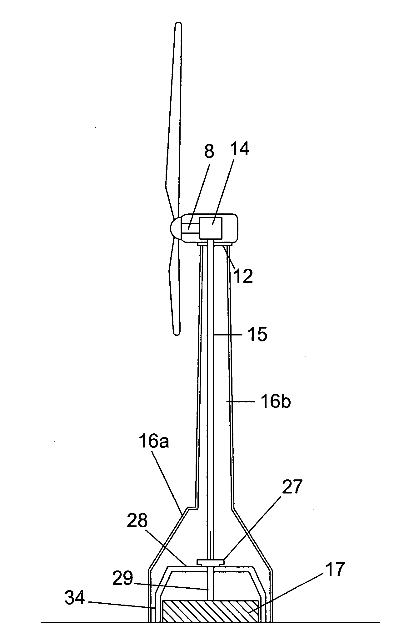
[0055]FIG. 4 shows the subject invention. The rotor (of which two of the 3 blades are shown) is connected via a horizontal shaft 8 to gear box 14. Gear box 14 converts horizontal axis rotation from the rotors to a vertical axis rotation for a downward extending shaft 15. Shaft 15 extends downward to thrust bearing 27. 12 is the yaw mechanism. In this embodiment, the yawing mechanism is shown at the top of the tower similar to conventional turbines. The tower cross-section is conventionally round in shape and only the nacelle turns during yaw adjustments. Thrust bearing 27 is supported by a mezzanine support system depicted by platform 28 and support members 34. Lower connecting shaft 29 links shaft 15 through thrust bearing 27 to direct drive generator 17. Lower tower housing 16a enlarges near the base of the tower to enclose the operating components located inside. Direct-drive generators are one method of converting rotational shaft torque into electricity. Upper tower portion 16b...

second embodiment

[0057]FIG. 5 shows the subject invention. The rotor (of which two of the 3 blades are shown) is connected via a horizontal shaft 8 to gear box 14. Gear box 14 converts horizontal axis rotation from the rotors to a vertical axis rotation for a downward extending shaft 15. Shaft 15 extends downward through yaw mechanism 12 to thrust bearing 27. Thrust bearing 27 is supported by a mezzanine support system depicted by platform 28 and support members 30. Lower connecting shaft 29 links shaft 15 through thrust bearing 27 to transmission 18. The transmission is designed to increase rotational mechanical advantage from vertical shaft 15. It is envisioned that in one embodiment of the subject invention transmission 18 would increase rotation by a ratio of 1:30. Transmission 18 is connected to generator 19 for the production of electrical power. Combination transmission-generator sets can be more cost effective to manufacture and require less room than direct-drive generators. Tower housing 1...

third embodiment

[0058]FIG. 6 shows the subject invention. The rotor (of which two of the 3 blades are shown) is connected via a horizontal shaft 8 to gear box 14. Gear box 14 converts horizontal axis rotation from the rotors to a vertical axis rotation for a downward extending shaft 20. Shaft 20 extends downward through yaw mechanism 12 to thrust bearing 27. Thrust bearing 27 is supported by a mezzanine support system depicted by platform 28 and support members 30. Lower connecting shaft 29 links shaft 20 through thrust bearing 27 to transmission 18. Transmission 18 is connected to generator 19 for the production of electrical power. In order to prevent warping or misalignment of shaft 20 sleeve 22 surrounds the shaft. Sleeve 22 is supported independently from shaft 20 by a second mezzanine support structure depicted by platform 32 and support members 31. Shaft 20 is constructed from at least two lengths and joined at joint 21. Taller towers will likely employ multiple shaft lengths 20 joined at re...


PUM


Abstract

A wind turbine utilizes a rotor assembly rotating about a substantially horizontal shaft, wherein said rotational motion is converted to a substantially vertical rotational motion through a shaft extending down from the nacelle located near the top of the tower structure to a mechanical room located at a lower altitude relative to the top of the tower. Said lower mechanical room houses some of the large heavy operational components of the turbine such that the turbine is not as top heavy as conventional turbines, and maintenance of the turbine is improved through ease of access to the lower altitude mechanical room.

Description

CROSS-REFERENCE TO RELATED APPLICATIONS[0001]This application claims priority to U.S. Provisional Patent Application No. 61 / 208,752, filed Feb. 28, 2009, which is hereby incorporated by reference and made a part hereof.FEDERALLY SPONSORED RESEARCH OR DEVELOPMENT[0002]Not Applicable.TECHNICAL FIELD[0003]The subject invention is related to the industry of alternative energy production and more specifically the industry of wind turbines.BACKGROUND OF THE INVENTION[0004]Wind turbines are well known mechanical devices used for hundreds of years to perform various mechanical works. The application and use of wind turbines to generate electricity was a natural and obvious application of turbines as soon the need for and availability of electricity was developed. Since the initial uses of turbines for generating electric power first appeared, many improvements and efficiencies have been applied to turbine technology.[0005]Traditional turbines have at least one rotor blade mounted on a hub r...

Claims


Application Information

Patent Timeline
IPC IPC(8): H02P9/06F03D11/02
CPCF03D11/04F05B2240/40F05B2240/80F03D11/02Y02B10/30Y02E10/726Y02E10/728F05B2260/96F03D15/00F03D13/20Y02E10/72F03D1/00
Inventor MOSER, GEORGELINN, RANDY W.WALWORTH, VANWHITAKER, CRAIG S.
Owner ENER2
Why Eureka
Try Eureka