Dual band infrared continuous zoom lens

a continuous zoom and infrared technology, applied in the field of optics, can solve the problems of complex optical design of the dual band system, difficult for systems that require significant focal length changes, etc., and achieve the effect of compact optical operating system

Inactive Publication Date: 2012-06-28
UNITED STATES OF AMERICA THE AS REPRESENTED BY THE SEC OF THE ARMY
View PDF8 Cites 31 Cited by
  • Summary
  • Abstract
  • Description
  • Claims
  • Application Information

AI Technical Summary

Benefits of technology

[0006]In another aspect, an exemplary optical operating system is disclosed based on an optical lens system having an optical lens imager capable of a variable focal length configured with an exemplary reflective afocal of a like magnification. Said optical operating system comprises the steps of: light enters the optical lens system via the reflective afocal; said light is first reflected off of a primary mirror, wherein said primary mirror is a concave parabolic off-axis mirror; said first reflected light is second reflected from a secondary mirror, wherein said secondary mirror is a convex off-axis parabolic mirror; said second reflected light from said secondary mirror is passed to a fold mirror; said light from said fold mirror is then reflected from a tertiary mirror, wherein said tertiary mirror is an off-axis concave parabolic mirror, and wherein there is an intermediate image plane between the fold mirror and the tertiary mirror; and said light reflected from said tertiary mirror is reflected off another fold mirror to be passed to said optical lens imager of a configured field of view. Said another fold mirror is disposed between the optical lens imager and the reflective afocal to achieve a compact optical operating system.
[0007]Yet, in another aspect, arm exemplary continuous-zoom dual spectral-band optical lens imager is disclosed based on infrared optical materials. Such an exemplary continuous-zoom dual spectral-band optical lens imager comprises a first lens based on zinc selenide and having an aspheric front surface; a second lens based on germanium and having spherical front and back curvatures; a third lens based on barium fluoride and having spherical front and back curvatures, wherein the first, second and third lenses form a triplet; a fourth lens based on zinc selenide and having a spherical first surface and aspheric second surface; a fifth lens based on germanium and having a spherical first surface and spherical second surface, wherein said fifth lens is moveably configured as a first zoom lens to moveably effect a focal length without changing an image plane location for either of the dual spectral bands; a six lens based on zinc selenide and having spherical first and second surfaces, wherein said sixth lens is moveably configured as a second zoom lens; a seventh lens based on barium fluoride and having spherical front and back surfaces; an eighth lens based on zinc selenide and having an aspheric first surface and a spherical second surface; and a dewar window based on an infrared transmitting material such as germanium; and a focal plane array. Said dewar window is configured to provide a vacuum seal to a dewar at cryogenic temperatures. Said focal plane array is either a dual band focal plane array or a broad band focal plane array housed in said dewar. An aperture stop or a cold stop is disposed between said dewar window and said focal plane array to determine a solid angle of the optics for each portion of said focal plane array. A pupil formed by the aperture stop is reimaged in-front of the first lens to form an entrance pupil for all fields of view.

Problems solved by technology

However, a dual band system requires a more complex optical design because of the need to image both spectral bands at the same image plane even though this is not the natural tendency of the optics.
This is very difficult for systems that require significant focal length changes.

Method used


Image

  • Dual band infrared continuous zoom lens
  • Dual band infrared continuous zoom lens
  • Dual band infrared continuous zoom lens

Examples


Embodiment Construction

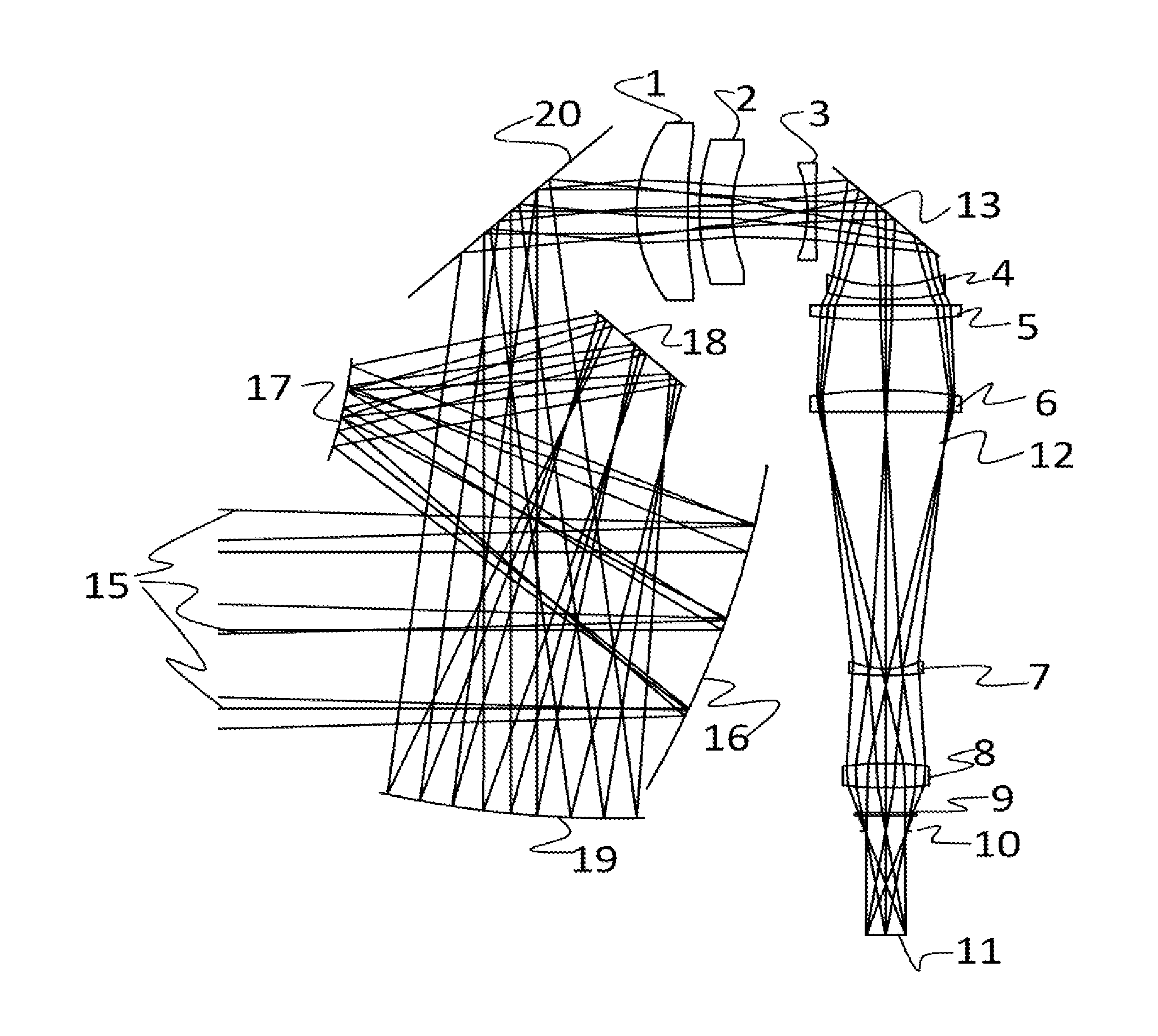
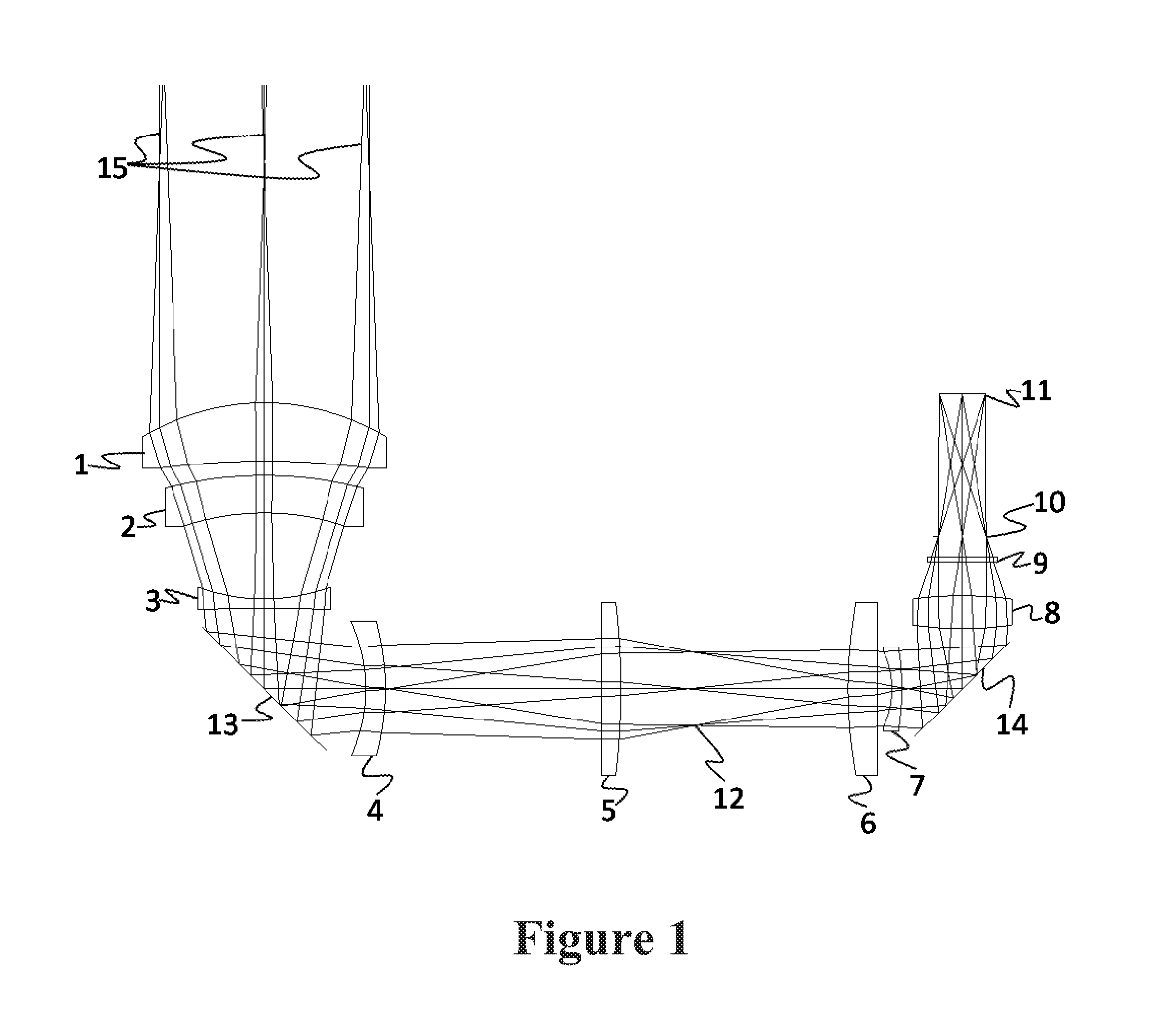
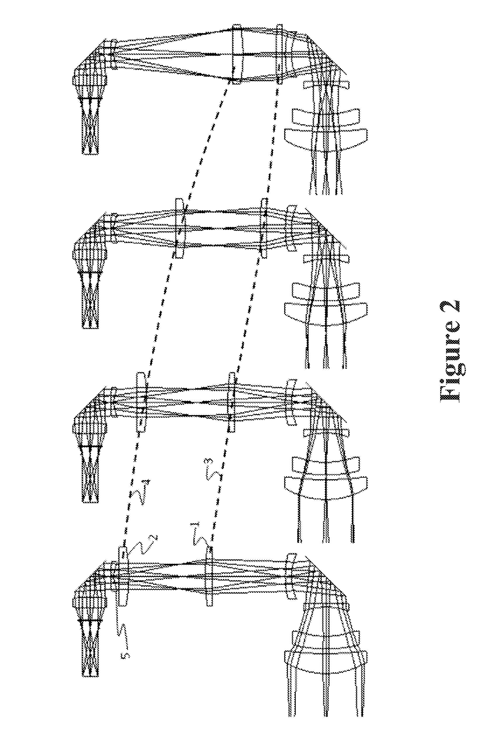
[0024]An exemplary optical system as shown in FIG. 1 comprises eight infrared imaging lenses that all transmit over the wavelengths 3.5-11.0 microns and form a collocated image plane for the MWIR (3.5-5.0 microns) and LWIR (7.5-11.0 microns) spectral bands. The lens arrangement can have six stationary lenses, and two lenses that move in an axial fashion. The lens arrangement is configured as an imager to utilize a cold stop inside the dewar to act as the aperture stop of the system and control the stray light from reaching the FPA, as is typically configured in a cooled infrared system. The pupil is reimaged from the cold stop to near the first lens of the system to minimize the size of the lens. The optic is designed to operate at an f / number of 3.0 and provides a focal length range from 38 mm to 130 mm for a 640×480 element focal plane array with micron square pixels. This has an equivalent image plane diameter of 16 mm, and results in a horizontal field of view range of 5.6-19.1 ...


PUM


Abstract

A continuous zoom lens arrangement can image MWIR and LWIR spectral bands to a common image plane. Such an exemplary optical system comprises eight infrared imaging lenses that all transmit over the wavelengths 3.5-11.0 microns and form a collocated image plane for the MWIR and LWIR spectral bands. The lens has six stationary lenses, and two lenses that move in arm axial fashion. A cold stop inside the dewar can act as the aperture stop of the system and control the stray light from reaching the FPA. The pupil is reimaged from the cold stop to near the first lens of the system to minimize the size of the lens. The optic is designed to operate at an f/number of 3.0 and provides a focal length range from 38 mm to 130 mm for a 640×480 element focal plane array with 20 micron square pixels. This has an equivalent image plane diameter of 16 mm. Such an optical system can work with a cold shield height of about 29.46 mm. The range in focal length result in an overall zoom change of 3.42×.

Description

GOVERNMENT INTEREST[0001]The invention described herein may be manufactured, used, sold, imported, and / or licensed by or for the Government of the United States of America.FIELD OF THE INVENTION[0002]This invention relates in general to optics, and more particularly to dual-band infrared continuous zoom lens system.BACKGROUND OF THE INVENTION[0003]With the development of dual band focal plane arrays which image both the mid-wavelength infrared (MWIR) and long-wavelength infrared (LWIR) spectral bands simultaneously at the same image plane, the development of various types of optical systems has been required. In order to keep the same capabilities as a single band system (i.e., MWIR only), it is necessary to develop similar types of optical systems. One useful type of optical system is a continuous zoom lens arrangement which enables FOV changing from the lenses shortest focal length to its longest focal length, and every focal length in between with good optical performance. This h...

Claims


Application Information

Patent Timeline
Patent Type & Authority Applications(United States)
IPC IPC(8): G02B17/08G02B13/14G02B15/14
CPCG02B13/146G02B17/0848G02B23/12G02B17/0642G02B17/0832G02B17/0896G02B9/64G02B13/14
Inventor VIZGAITIS, JAY N.
Owner UNITED STATES OF AMERICA THE AS REPRESENTED BY THE SEC OF THE ARMY
Why Eureka
Try Eureka