Membrane electrode assembly, fuel cell with the same, and fuel cell generating system

a technology of membrane electrodes and fuel cells, applied in the direction of solid electrolyte fuel cells, fuel cells, cell components, etc., can solve the problems of increasing the loss of auxiliary power sources, limiting the absorption effect, and difficult to obtain the effect of removing formic acid for a long period of time, so as to reduce the quantity of discharged formic acid and reduce system efficiency

Inactive Publication Date: 2012-06-28
HITACHI LTD
View PDF3 Cites 4 Cited by
  • Summary
  • Abstract
  • Description
  • Claims
  • Application Information

AI Technical Summary

Benefits of technology

[0016]The present invention makes it possible to provide a membrane electrode assembly for a fuel cell and a fuel cell system that can reduce the quantity of discharged formic acid for a long period of time without lowering system efficiency.

Problems solved by technology

In the method of using the absorbent however, a capacity of the absorbent has itself limit and hence it is difficult to obtain the effect of removing formic acid for a long period of time.
Then in the method of installing the catalytic filter in the exhaust gas pipe, since the filter acts as resistance to flow of the exhaust gas, a blower capacity has to be increased, the loss by an auxiliary power source increases, and hence the efficiency of a fuel cell system lowers.

Method used


Image

  • Membrane electrode assembly, fuel cell with the same, and fuel cell generating system
  • Membrane electrode assembly, fuel cell with the same, and fuel cell generating system
  • Membrane electrode assembly, fuel cell with the same, and fuel cell generating system

Examples


example 1

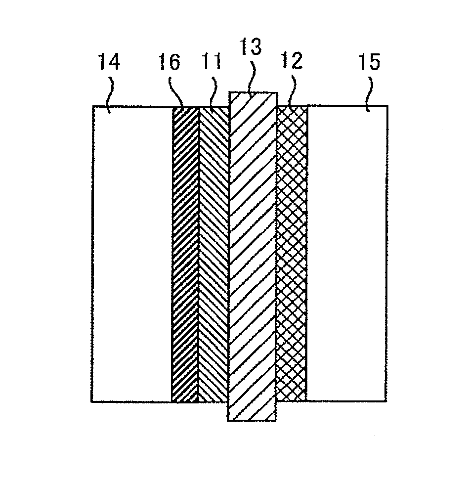
[0048]In the present example, produced is the membrane electrode assembly for the fuel cell shown in Fig.

[0049]Slurry for the anode is produced by mixing platinum ruthenium supported with carbon black, Nafion (registered trademark of Dupont) as the solid polymer electrolyte, propanol, and water, and then the slurry is stirred for 24 hours with a stirrer. Further, slurry for the formic acid oxidation electrode is produced by mixing palladium supported with carbon black, Nafion, propanol, and water, and then the slurry is stirred for 24 hours with a stirrer. Furthermore, slurry for the cathode is produced by mixing platinum supported with carbon black, Nafion, propanol, and water, and then the slurry is stirred for 24 hours with a stirrer.

[0050]The slurry for the anode is applied to one side of the solid polymer electrolyte membrane by spray coating, and the slurry for the formic acid oxidation electrode is applied to one side of the anode so that the mass of palladium may be 0.2 mg / c...

example 2

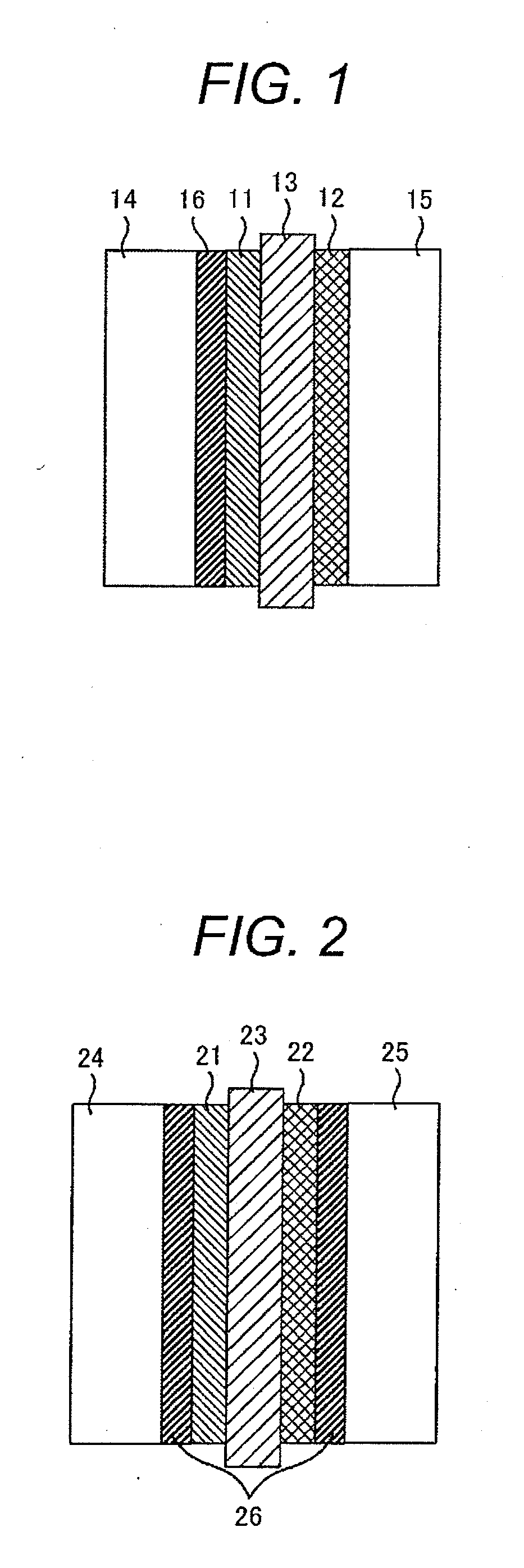
[0052]In the present example, produces is the membrane electrode assembly for a fuel cell shown in FIG. 2 is produced.

[0053]Firstly, in the same manner as Example 1, slurry for the anode, slurry for the formic acid oxidation electrode, and slurry for the cathode are produced and stirred for 24 hours with a stirrer respectively.

[0054]The slurry for the anode is applied to one side of the solid polymer electrolyte membrane by spray coating, and the slurry for the formic acid oxidation electrode is applied to one side of the anode by spray coating so that the mass of palladium may be 0.2 mg / cm2 per unit electrode projected area. Successively, the slurry for the cathode is applied to another side of the solid polymer electrolyte membrane by spray coating, the slurry for the formic acid oxidation electrode is applied to one side of the anode and one side of the cathode by spray coating and then hot press is applied to the layered of them at 120° C. Here, in the same manner as Example 1, ...


PUM


Abstract

A membrane electrode assembly for a fuel cell comprises a solid polymer electrolyte membrane, an anode being formed on one side of the solid polymer electrolyte membrane and containing a catalyst and a solid polymer electrolyte, a cathode being formed on another side of the solid polymer electrolyte membrane and containing a catalyst and a solid polymer electrolyte, an anode gas diffusion layer formed on one side of the anode, and a cathode gas diffusion layer formed on one side of the cathode. In addition, a formic acid oxidation electrode containing palladium and a solid polymer electrolyte is formed between the anode gas diffusion layer and the anode.

Description

CLAIM OF PRIORITY[0001]The present application claims priority from Japanese Patent application serial no. 2010-289097, filed on Dec. 27, 2010, the contents of which are hereby incorporated by references into this application.FIELD OF THE INVENTION[0002]The present invention relates to a membrane electrode assembly, a fuel cell with the same, and a fuel cell generating system.BACKGROUND OF THE INVENTION[0003]As recent electronic technologies progress, the amount of information increases and such increasing information is required to be processed more speedy and more functionally. Hence, needs are directed toward an electric source with a high output density and a high energy density, namely the electric source with a long continuous driving time.[0004]Furthermore, the necessity of a small generator with electric chargeless, namely a micro-generator capable of supplying a fuel easily, is increasing. From such background, the importance of a fuel cell has been studied.[0005]A fuel cel...

Claims


Application Information

Patent Timeline
IPC IPC(8): H01M8/10H01M4/90H01M4/92
CPCH01M4/8657H01M4/8828H01M4/92H01M4/921Y02E60/523H01M8/0662H01M8/1011H01M2008/1095H01M8/04186Y02E60/50
Inventor SUZUKI, SHUICHIONUMA, ATSUHIKOKAWAJI, JUNTAKAMORI, YOSHIYUKIANDOH, SHINSUKEMIZUKAMI, TAKAAKI
Owner HITACHI LTD
Why Eureka
Try Eureka