Eureka AIR delivers breakthrough ideas for toughest innovation challenges, trusted by R&D personnel around the world.

Fast transportable drilling rig system

Active Publication Date: 2012-07-05
SCHLUMBERGER TECH CORP
View PDF4 Cites 69 Cited by
  • Summary
  • Abstract
  • Description
  • Claims
  • Application Information

AI Technical Summary

Benefits of technology

[0013]The present invention provides a substantially improved drilling rig system. In one embodiment, a drilling mast transport skid is provided comprising a frame positionable on a transport trailer. A forward hydraulically actuated slider, and a rear hydraulically actuated slider are located on the frame. The sliders are movable in perpendicular relationship to the frame. An elevator is movably located between the rear slider and the mast supports (or equivalently between the rear slider and frame) for vertically elevating the mast relative to the frame. A carriage is movably located between the frame and the forward slider for translating the forward slider along the length of the frame. A mast section of a drilling rig may be positioned on the sliders, such that controlled movement of the sliders, the elevator and the carriage can be used to position the mast section for connection to another structure.
[0023]In another embodiment, each wing bracket of the drilling rig further comprises a wing cylinder attached between the interior of the lower mast section and the arm of the wing bracket. Actuation of the wing cylinder moves the wing bracket between the deployed and stowed positions, without the need to have workers scaling the mast to lock the wing in position.

Problems solved by technology

This requirement results in extensive disassembly of full-size drilling rigs to maintain a maximum transportable width and transportable height (mast depth) with further restrictions on maximum weight, number and spacing of axles, and overall load length and turning radius.
These transportation constraints vary from state to state, as well as with terrain limitations.
These constraints can limit the size and capacity of rigs that can be transported and used, conflicting with the subterranean requirements to drill deeper, or longer reach horizontal wells, more quickly, requiring larger rigs.
Larger rigs require a wider base structure for strength and wind stability, and this requirement conflicts with the transportability constraint and the time and cost of moving them.
These rigs have reduced rig transport and rig-up time; however, substructure hydraulics are still required and the three-step lifting process and lower mast lifting capacity remain compromised in these configurations.
These add to rig-up and rig-down time, weight, and transportation requirements, encumber rig floor access, and may still require cranes for rig-up.
Movement of rig masts from transport trailers to engagement with substructures remains time consuming and difficult.
Also, rig lifting supports create a wider mast profile, which limits the size of the structure support itself due to transportation regulations, and thus the wind load limit of the drilling rig.
However, limiting the height of the collapsed substructure restricts the overall length of retracted raising cylinders in conventional systems.
It further increases the lift capacity requirement of the raising cylinder due to the disadvantageous angle created by the short distance from ground to drilling floor in the collapsed position.
This increases design and construction costs, as well as the problems associated with maintaining inventories of the expensive raising cylinders in multiple sizes.
Technological and economic barriers have prevented the development of a drilling rig capable of achieving these goals.
Conventional prior art drilling rig configurations remain manpower and equipment intensive to transport and rig-up.
Alternative designs have failed to meet the economic and reliability requirements necessary to achieve commercial application.
Quick rig-down and transportation of these rigs have proven to be particularly difficult.

Method used


Image

  • Fast transportable drilling rig system
  • Fast transportable drilling rig system
  • Fast transportable drilling rig system

Examples


Embodiment Construction

[0073]The following description is presented to enable any person skilled in the art to make and use the invention, and is provided in the context of a particular application and its requirements. Various modifications to the disclosed embodiments will be readily apparent to those skilled in the art, and the general principles defined herein may be applied to other embodiments and applications without departing from the spirit and scope of the present invention. Thus, the present invention is not intended to be limited to the embodiments shown, but is to be accorded the widest scope consistent with the principles and features disclosed herein.

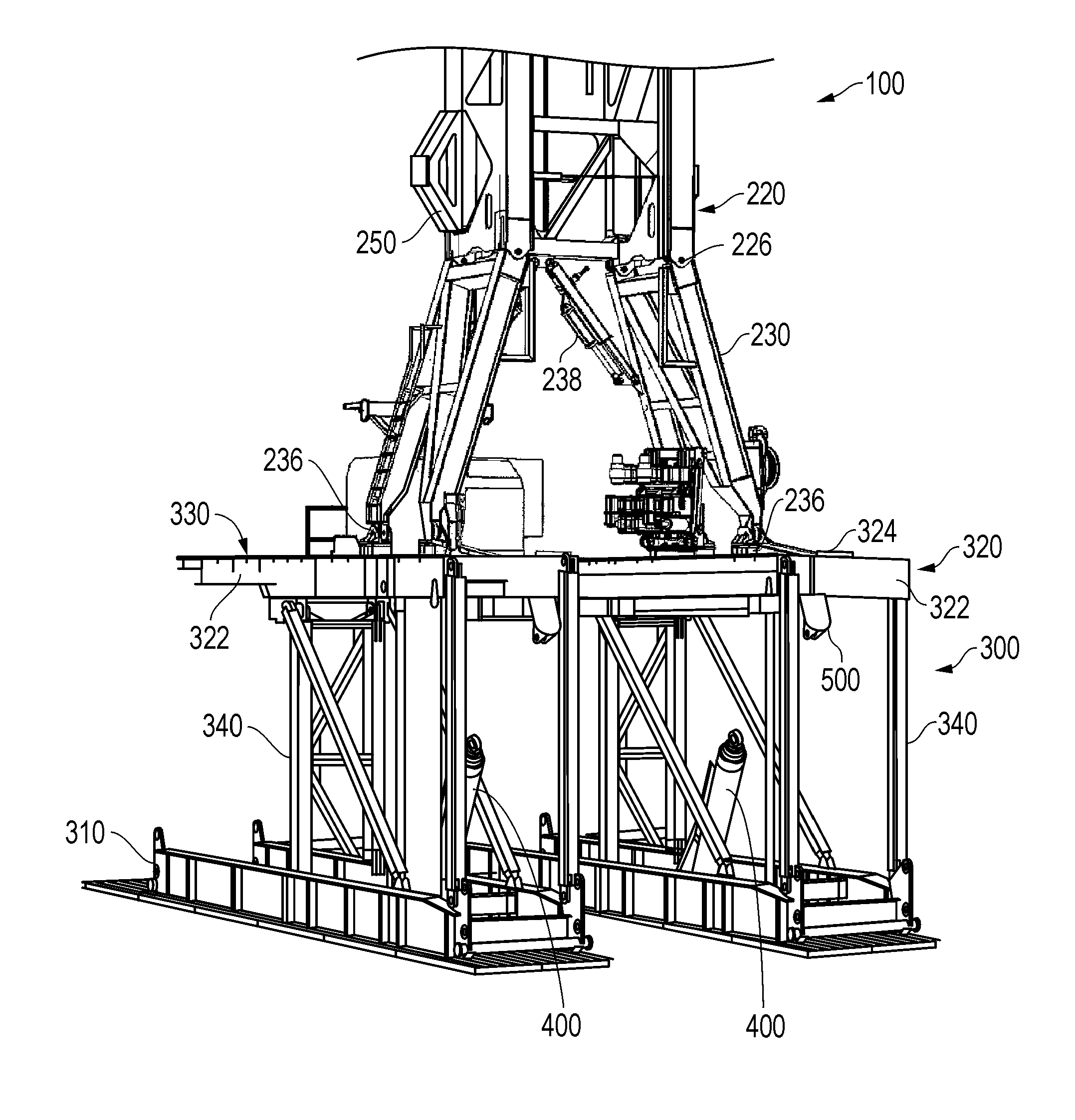
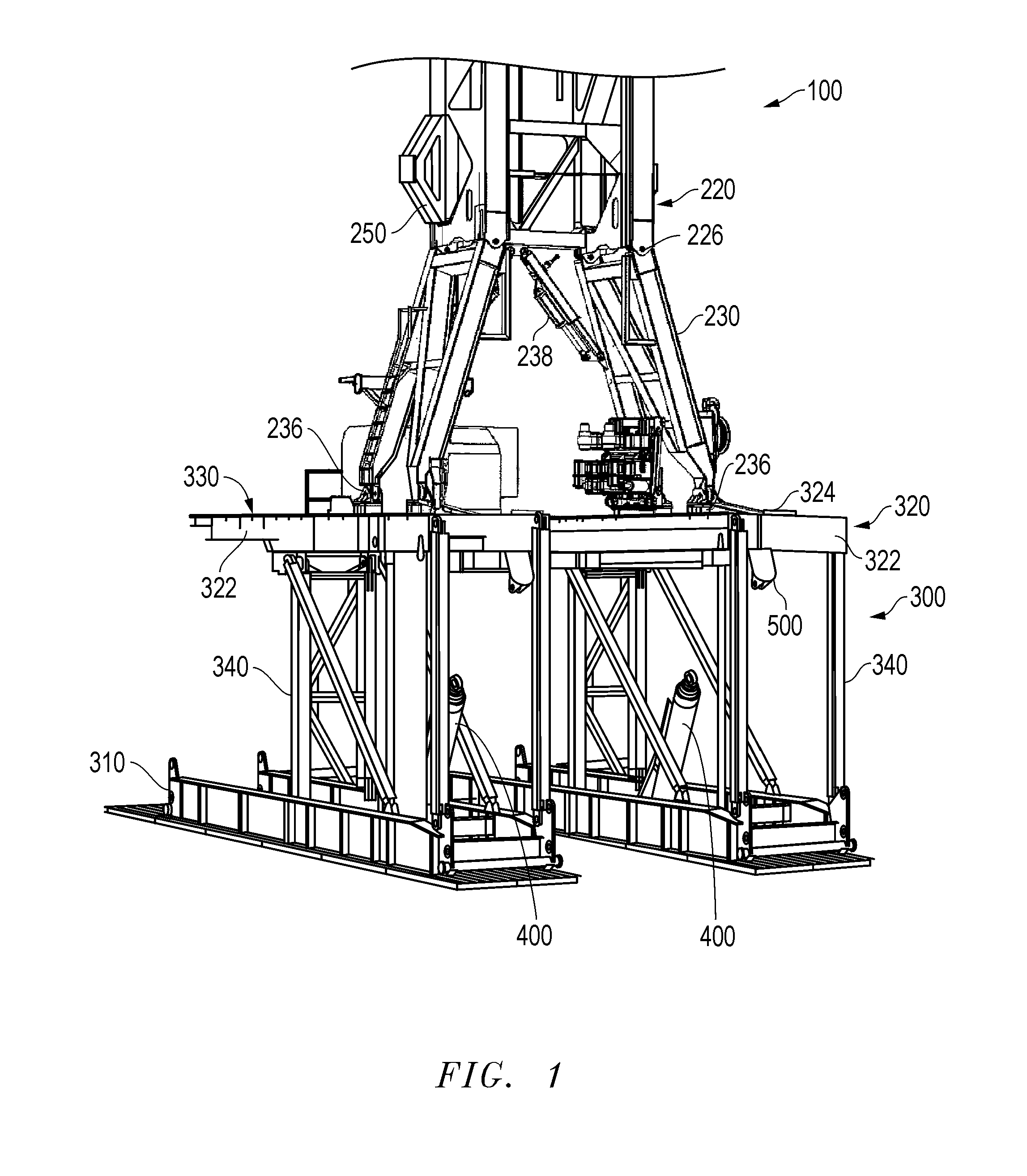
[0074]FIG. 1 is an isometric view of a drilling rig assembly 100 including features of the invention. As seen in FIG. 1, drilling assembly 100 has a lower mast section 220 mounted on top of a substructure 300.

[0075]Mast leg pairs 230 are pivotally attached to lower mast section 220 at pivot connections 226. Mast leg cylinders 238 may be connect...


PUM


Abstract

The present invention discloses a high-capacity drilling rig system that includes novel design features that alone and more particularly in combination facilitate a fast rig-up and rig-down with a single set of raising cylinders and maintains transportability features. In particular, a transport trailer is disclosed having a first support member and a drive member which align the lower mast portion with inclined rig floor ramps and translate the lower mast legs up the ramps and into alignment for connection. A pair of wing brackets is pivotally deployed from within the lower mast width for connection to the raising cylinder for raising the mast from a horizontal position into a vertical position. A cantilever is pivotally deployed from beneath the rig floor to a position above it for connection to the raising cylinder for raising the substructure from a collapsed position into the erect position.

Description

TECHNICAL FIELD OF INVENTION[0001]The present invention relates to a new rig mast, substructure, and transport trailer for use in subterranean exploration. The present invention provides rapid rig-up, rig-down and transport of a full-size drilling rig. In particular, the invention relates to a self-erecting drilling rig in which rig-up of the mast and substructure may be performed without the assistance of a crane. The rig components transport without removal of the drilling equipment including top drive with mud hose and electrical service loop, AC drawworks, rotary table, torque wrench, standpipe manifold, and blow out preventers (BOP), thus reducing rig-up time and equipment handling damage.BACKGROUND OF THE INVENTION[0002]In the exploration of oil, gas and geothermal energy, drilling operations are used to create boreholes, or wells, in the earth. Drilling rigs used in subterranean exploration must be transported to the locations where drilling activity is to be commenced. These...

Claims


Application Information

Patent Timeline
IPC IPC(8): E21B15/00E04B1/343E04H12/00E04H12/34
CPCE04H12/187E21B15/00E04H12/345
Inventor TREVITHICK, MARK W.JAMISON, DARRELL E.RODRIGUEZ, GUS E.ORGERON, KEITH J.
Owner SCHLUMBERGER TECH CORP
Why Eureka
Eureka Blog
Learn More