Li-ion battery array for vehicle and other large capacity applications

a technology for lithium-ion batteries and vehicles, applied in battery/fuel cell control arrangements, process and machine control, instruments, etc., can solve the problem of significant portion of the overall weight of electric vehicles, and achieve the effect of reducing the time necessary, and reducing the cost of operation

Inactive Publication Date: 2010-05-13
BOSTON POWER INC
View PDF19 Cites 181 Cited by
  • Summary
  • Abstract
  • Description
  • Claims
  • Application Information

AI Technical Summary

Benefits of technology

[0011]The switching elements used to connect a module into the series string and to connect the charging circuitry to each module are preferably of the solid state variety implemented as Field Effect Transistors (FETs) as opposed to mechanical relays. FET switches have higher reliability because there is no mechanical wear. Additionally, an FET's turn-on and turn-off times are faster than mechanical equivalents. FET switches are frequently more compact devices and are well suited for low profile assembly on a printed circuit board.
[0012]The charging circuitry may be used to charge the battery modules from a current source, preferably an alternating current source in a fully electric or plug-in hybrid system. Multiple individual chargers may each be coupled to one or more battery modules. The multiple individua

Problems solved by technology

Battery powered electric vehicles may require several thousands of battery cells in order to ope

Method used


Image

  • Li-ion battery array for vehicle and other large capacity applications
  • Li-ion battery array for vehicle and other large capacity applications
  • Li-ion battery array for vehicle and other large capacity applications

Examples


Embodiment Construction

[0023]A description of example embodiments of the invention follows.

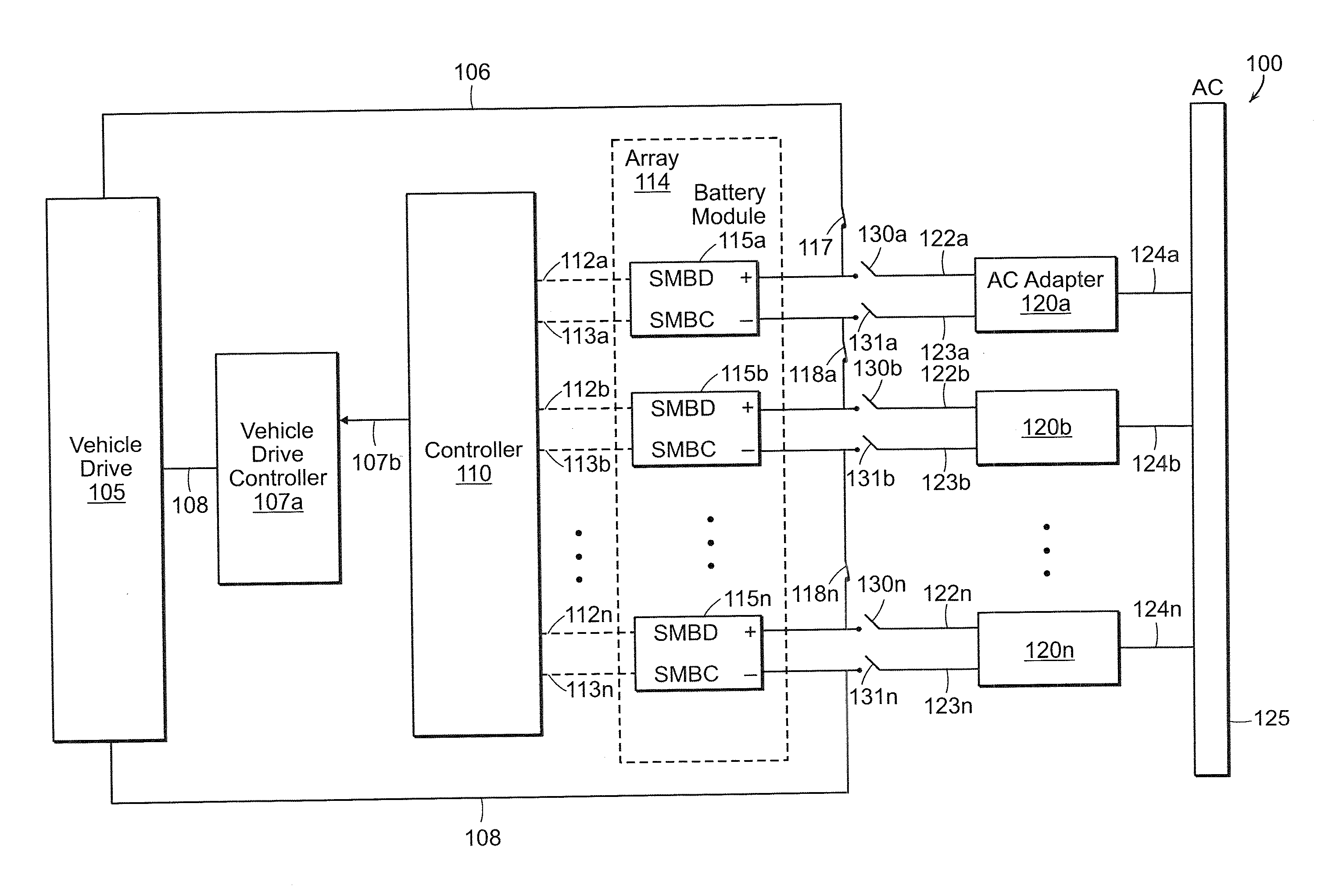
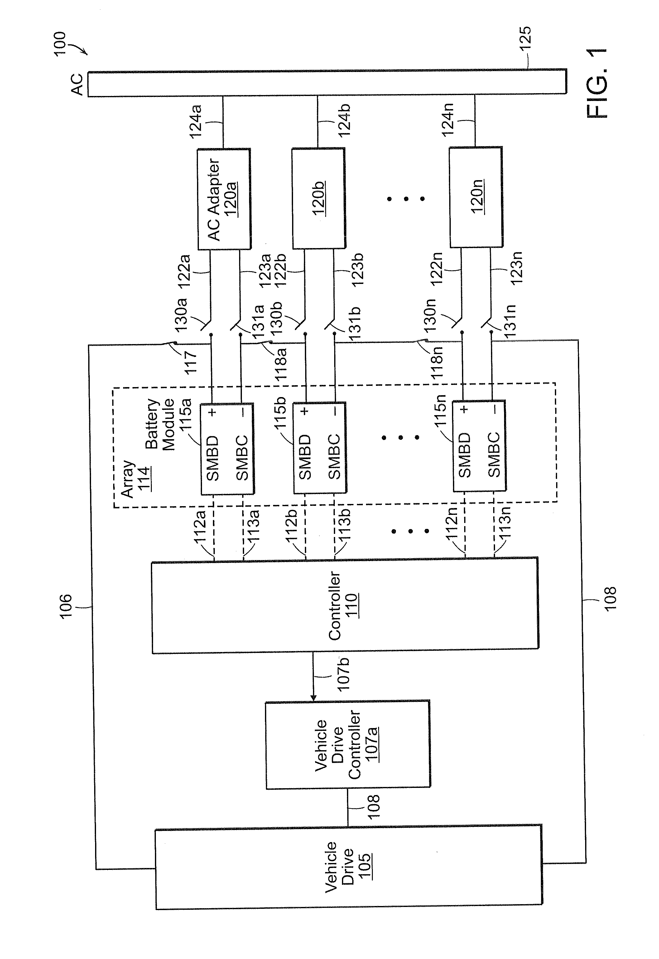
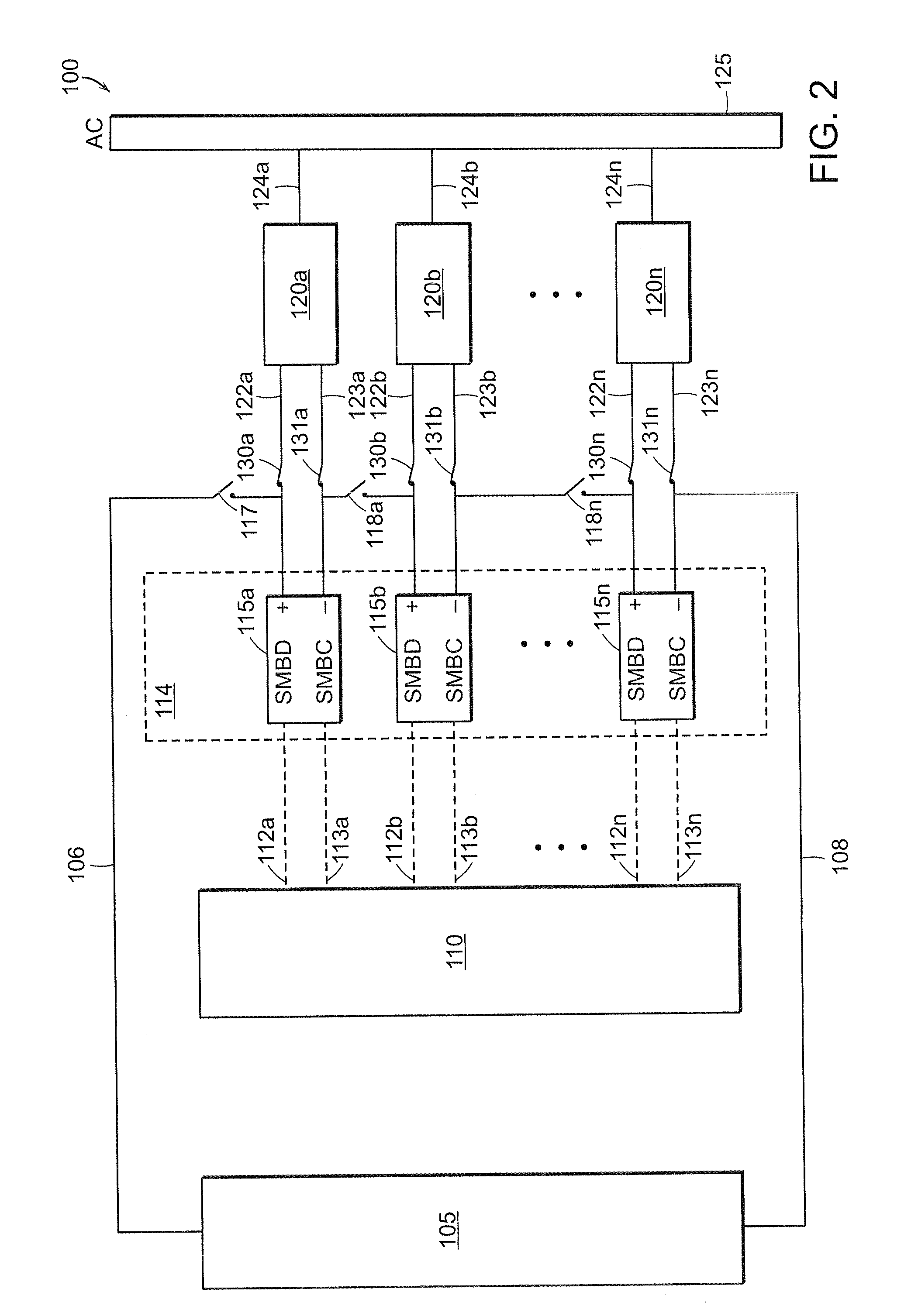
[0024]Current notebook PC battery packs already contain electronics that control the charging, discharging, balancing, and monitoring of lithium-ion battery cells. The present disclosure incorporates the primary features of the existing technology in notebook PC battery packs to provide “battery modules” in the vehicle battery. Each module may contain several lithium-ion cells and electronics to control the charging, discharging, monitoring, balancing, and protective modes of those cells. The array may also include the necessary AC adapters to provide the required. DC voltage to charge itself (the size of which would be optimized for the desired charging time of the battery modules). The battery modules of the array may be controlled by the module management electronics and charged using low-voltage by a power adapter, all of which are connected to a high-voltage power bus. A network of switches allows those battery...


PUM


Abstract

A large battery array, particularly for use in an electric vehicle, is formed of multiple modules, each containing plural battery cells and module management electronics. Each battery module has a nominal output voltage in the range of about 5 volts to about 17 volts. A controller communicates with individual battery modules in the array and controls switching to connect the modules in drive and charging configurations. The module management electronics monitor conditions of each battery module, including the cells it contains, and communicates these conditions to the controller. The module management electronics may place the modules in protective modes based upon the performance of each module in comparison to known or configurable specifications. The modules may be pluggable devices so that each module may be replaced if the module is in a permanent shutdown protective mode or if a non-optimal serviceable fault is detected.

Description

RELATED APPLICATIONS[0001]This application claims the benefit of U.S. Provisional Application No, 61 / 195,441, filed Oct. 7, 2008 and U.S. Provisional Application No. 61 / 176,707, filed May 8, 2009. The entire teachings of the above applications are incorporated herein by reference.BACKGROUND OF THE INVENTION[0002]Motor vehicles take several forms including motorcycles, automobiles, buses, trucks, or construction / military vehicles. Currently, the most commonly used motor is an internal combustion engine. An internal combustion engine is an engine in which fuel and an oxidizer, normally air, combust in a confined space (also known as a combustion chamber). The combustion creates gases at high temperatures and pressures. Internal combustion engines are primarily fueled by various types of petroleum derivatives. The combustion also creates exhaust, such as steam, carbon dioxide, particulate matter, and other chemicals.[0003]There are numerous effects caused by reliance on motor vehicles,...

Claims


Application Information

Patent Timeline
IPC IPC(8): G06F7/00H02J7/00
CPCB60L11/1851B60L11/1861B60L11/1866B60L2210/20H02J7/0014H02J7/1423Y02T90/16Y02T10/7011Y02T10/7044Y02T10/7055Y02T10/7061Y02T10/725Y02T10/7005B60L58/10B60L58/15B60L58/22Y02T10/70Y02T10/72
Inventor ONNERUD, PERMILNE, SCOTT D.CHAMBERLAIN, II, RICHARD V.WANG, SHIQUANSOUZA, CHAD
Owner BOSTON POWER INC
Why Eureka
Try Eureka