Cyclone induced sweeping flow separator

a flow separator and cyclone technology, applied in the field ofinertial separation, can solve the problems of limited efficiency and limited minimum streamline curvature of current cyclone technology, and achieve the effect of facilitating the formation of sharply curved streamlines, effective inertial separation of particles, and high acceleration

Active Publication Date: 2012-07-05
MOTAKEF ABBAS
View PDF3 Cites 29 Cited by
  • Summary
  • Abstract
  • Description
  • Claims
  • Application Information

AI Technical Summary

Benefits of technology

[0006]The present application describes a particle separator based on a cyclone induced sweeping flow. This cylindrical or conical shaped separator screen operates based on inertial separation of suspended particles in fluids. The separator screen comprises of multitude of parallel, evenly spaced, asymmetrically profiled, linear elements arranged in a cylindrical or conical shape parallel with the axis of the cylinder or cone. In one embodiment, the fluid mixed with particulates enters tangentially at the top end of the cylinder or cone through a high velocity jet. The cyclone effect is created by the rotational, helical path of the fluid inside of the cylindrical or conical separator screen. The spinning, rotating fluid sweeps the inner side of the separator, passing approximately perpendicularly over the linear elements and gaps between the elements. Part of the fluid will pass through the gaps of the separator to a collector-space that is an outer space, approximately coaxial with the separator-screen. The streamlines of the fluid passing through the gaps of the separator have sharp curvatures creating the acceleration conditions required for inertial separation of particulates. The particulates even those that are smaller than the openings of the separator screen—separate from the streamlines of the pass-through flow and continue on the helical path inside the cylinder. The pass-through fluid is clean while the rotating vortex flow inside the separator-screen is concentrated with particles. The spiraling flow sweeps the particles along the inner portion of the separator-screen and they are collected at the bottom cone and released from the cyclone. The separated, clean fluid leaves the cyclone from the coaxial collector space. The separator-screen elements may be wires, bars, narrow strips, blades, airfoils or other similar linear elements with a flow separation edge on the trailing end of the profile of the element. The separation edge facilitates a formation of sharply curved streamlines of the flow passing through the gaps of the separator-screen for high acceleration and effective inertial separation of particles. The protruding separation edge also facilitates a formation of gently curved un-separated sweeping streamlines that provide bridge effect, taking the particles over the gaps of the separator.
[0008]In another embodiment, the inertial separation screen is a rotating (non-stationary) component of the system. The separation screen is rotating around of its cylindrical axis, in counter direction of the rotation of the tangentially entered mixed-fluid. The counter directional rotation enhances the inertial separation effect of the system. The fluid mixed with particulates enters tangentially at the top end of the cylindrical vessel into the coaxial space between the rotating inertial separator screen and the wall of the cylinder vessel. The rotating fluid sweeps the outer side of the rotating separator screen, passing over the linear elements that are moving in counter direction. Part of the fluid will pass through the gaps of the separator to the central collector-space that is inside the separator-screen. The particles separate from the streamlines of the pass-through flow and continue on the helical path in the coaxial space outside the separator. The pass-through fluid is clean while the rotating vortex flow outside the separator screen is concentrated with particles. The spiraling cyclone-flow sweeps the particles along the outer portion of the separator-screen and they are collected at the bottom cone and released from the cyclone. The separated, clean fluid leaves the cyclone from the central collector space through an outlet pipe and port, located in the centerline of the apparatus.

Problems solved by technology

Wastewater and storm water may also carry large quantities of suspended solids.
The disadvantage of the currently known cyclone technology is that it has limited minimum streamline curvature (i.e. how small the curvature can be).
As smaller curvature generally results in better separation efficiency, therefore the current cyclone technology has limited efficiency because the curvature of the cyclone is limited to the radius of its cylinder.
Few of these recently developed separator systems employ sweeping flow to facilitate and improve the separation of suspended matter.

Method used


Image

  • Cyclone induced sweeping flow separator
  • Cyclone induced sweeping flow separator
  • Cyclone induced sweeping flow separator

Examples


Embodiment Construction

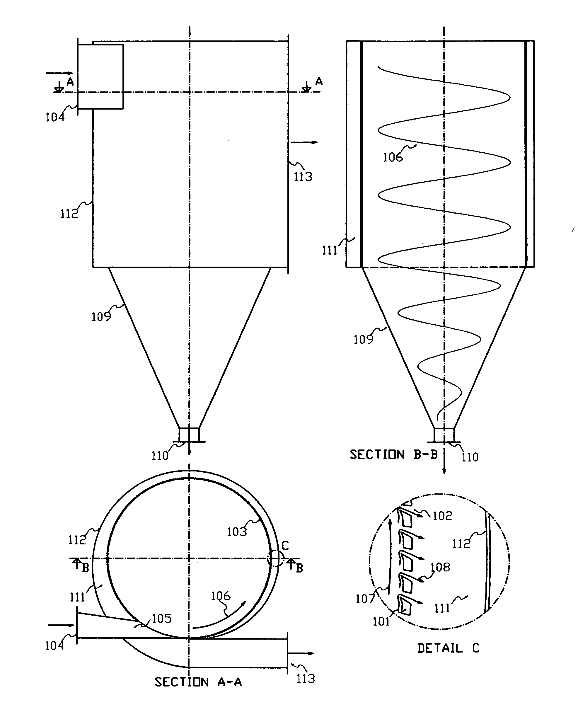
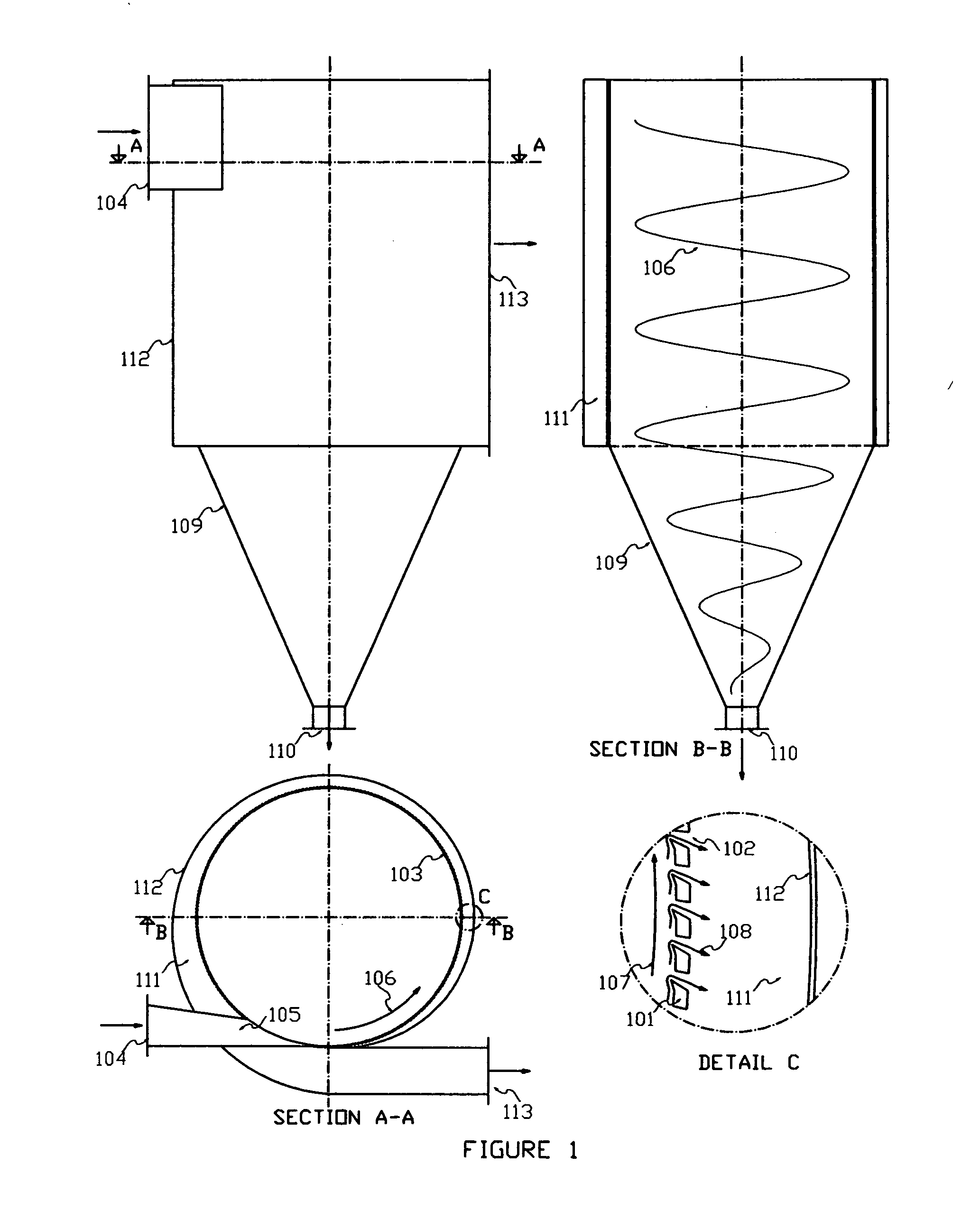
[0017]Referring now to the drawings, in which like numerals indicate like elements, FIG. 1 shows cross sectional views and details of one preferred embodiment of the cyclone induced sweeping flow separator screen. Multitude of parallel, asymmetrically profiled linear elements 101 are evenly spaced, separated by gaps 102 to form the linear grid of the cylindrical or slightly conical face of the separator-screen 103. The mixed flow of fluid (gas or liquid) and particles enters the apparatus through the inlet port 104 at the top portion of the device. The inlet nozzle 105 accelerates and directs the flow tangentially to the face of the screen. This tangential entry generates a spinning, rotating, swirling motion of the fluid 106 inside the separator-screen that is also referred as cyclone effect. The rotating fluid sweeps the cylindrical face of the screen perpendicularly crossing 107 its linear grid elements 101. Some of the fluid will pass through the gaps of the separator screen, wi...


PUM

PropertyMeasurementUnit
gap-sizeaaaaaaaaaa
width sizeaaaaaaaaaa
velocityaaaaaaaaaa

Abstract

The cylindrical or conical shaped particle separator operates based on cyclone-induced flow sweeping the face of the cylindrical separator screen, creating inertial separation of suspended particles. The separator screen comprises of multitude of parallel, evenly spaced, asymmetrically profiled, linear, screen elements arranged in a cylindrical or conical grid-like shape parallel with the axis of the cylinder or cone. The cyclone effect is created by the rotational, helical path of the fluid inside or outside of the cylindrical or conical separator screen. The spinning, rotating fluid sweeps the inner or outer side of the stationary or rotating screen, passing approximately perpendicularly over the linear grid-like elements and gaps between the elements. The screen elements may be wires, bars, narrow strips, airfoil vanes or other similar linear elements with a flow separation edge on the trailing end of the profile of the element.

Description

TECHNICAL FIELD[0001]The present application relates generally to inertial separation of particulates suspended in or carried by fluids and specifically to, air filters, dust separators, clarifiers, cyclones, vacuum cleaners, precipitators, sifting screens, decanters, demisters, gaseous and fluid filtration devices alike.BACKGROUND OF THE INVENTION[0002]Separation of suspended particulates from fluids is a common filtration engineering task. Solid, semi-solid or gel-like particulates may be suspended or carried in a gases or liquids in motion. Small water droplets, spray-mist, sea salt, dust etc, may be suspended in the ambient air, carried by wind or blown by ventilation systems. Fly ash and unburned coal dust may be exhausted in the hot fumes of industrial boilers and combustors. Intakes of water treatment systems, desalination systems may have sand and suspended silt in the raw water. Wastewater and storm water may also carry large quantities of suspended solids. Various chemical...

Claims


Application Information

Patent Timeline
Patent Type & Authority Applications(United States)
IPC IPC(8): B01D29/54B01D50/00B01D29/60B01D45/16B01D33/06B01D33/27
CPCB01D46/0046B01D45/16B01D50/002B01D46/40B01D50/20
Inventor MOTAKEF, ABBAS
Owner MOTAKEF ABBAS
Why Eureka
Try Eureka