Circuit arrangement for creating microwave oscillations

a technology of circuit arrangement and microwave oscillation, which is applied in the direction of oscillator, pulse technique, pulse generator, etc., can solve the problems of reducing the overall quality factor of the electronic oscillator by the external resonator, and affecting the operation of the oscillator. achieve the effect of increasing the effective capacitan

Active Publication Date: 2012-07-05
KROHNE MESSTECHNICK GMBH & CO KG
View PDF3 Cites 4 Cited by
  • Summary
  • Abstract
  • Description
  • Claims
  • Application Information

AI Technical Summary

Benefits of technology

[0021]In the simplest case, the compensation capacitance can be implemented as a constant capacitance between two metal electrodes. This can occur in an integrated circuit either horizontally between two metal plates (called metal-isolator-metal=MIM) or the capacitance—usually in very finely structured processes—between two metal lines in the same plane in the vertical direction is used (called vertical-parallel-plate=VPP). These two solutions lead to a compensation capacitance with high quality.
[0025]A particularly preferred embodiment of the implementation of the compensation capacitance according to the invention is characterized in that reverse-biased pn-junctions—provided as compensation capacitances—are implemented in the same manner as the parasitic base collector capacitances of the transistors belonging to the electronic oscillator. This has different advantages:

Problems solved by technology

However, the influence of the outer load on the electronic oscillator, the load repercussion, cannot be compensated with phase control.
An insufficient decoupling of the electronic oscillator from the outer load results in that the outer load, which, for example, can be a longer connecting line, additionally acts as a resonator for the electronic oscillator.
However, this improvement of the quality factor is only effective at certain frequencies, at other frequencies the overall quality factor of the electronic oscillator is considerably downgraded by the external resonator.
Consequently, a modulation of the phase noise results via the frequency of the electronic oscillator.
A small change in the control voltage can lead to a sudden skip of the frequency of the electronic oscillator.
This can go so far that the tuning characteristic is not unambiguous, so that tuning in different direction leads to a hysteresis in the tuning characteristic.
As a result, the electronic oscillator can no longer be tuned smoothly.
In addition, a sudden switch of the load, for example, by switching between different antennae, can put the electronic oscillator out of tune.
However, even in electronic oscillators having phase control these skips as well as too strong phase noise can lead to the phase control no longer being capable of stabilizing the electronic oscillator, so that the entire circuit arrangement is no longer functional.
However, non-reciprocal components can only be implemented with considerable effort.
Integration on one chip is not possible with reasonable effort, integration on a printed circuit board is costly.
However, additional power is principally needed for operating an active decoupling, which then increases the overall power loss.
However, a Miller effect only occurs when a voltage amplifier occurs between the base nodes and the collector nodes of a transistor, which is not the case in many dimensions.
Especially in battery-operated circuit arrangements, the power provided is limited so that, in particular, the decrease in the required power dissipation has a positive impact.

Method used


Image

  • Circuit arrangement for creating microwave oscillations
  • Circuit arrangement for creating microwave oscillations
  • Circuit arrangement for creating microwave oscillations

Examples


Embodiment Construction

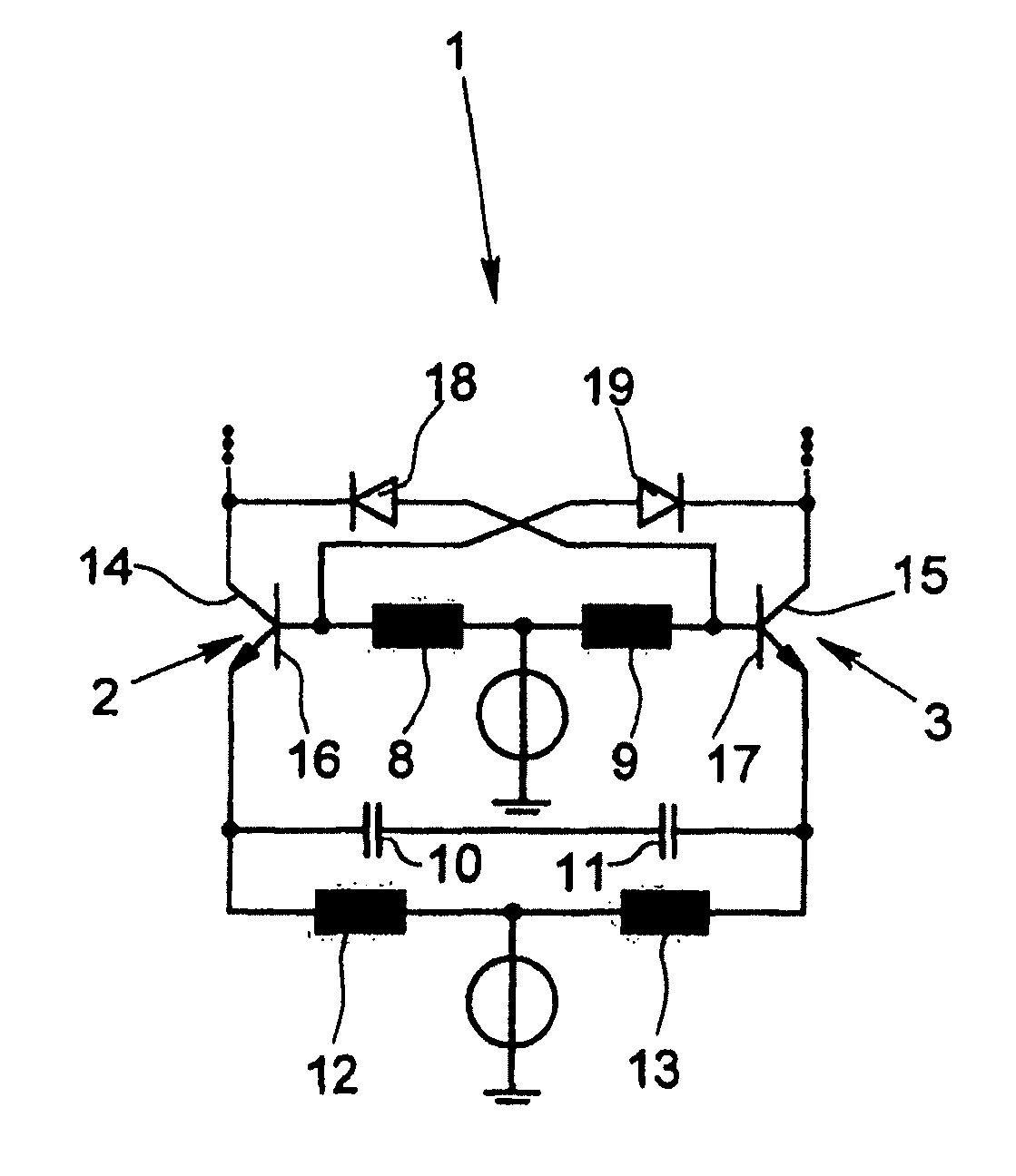
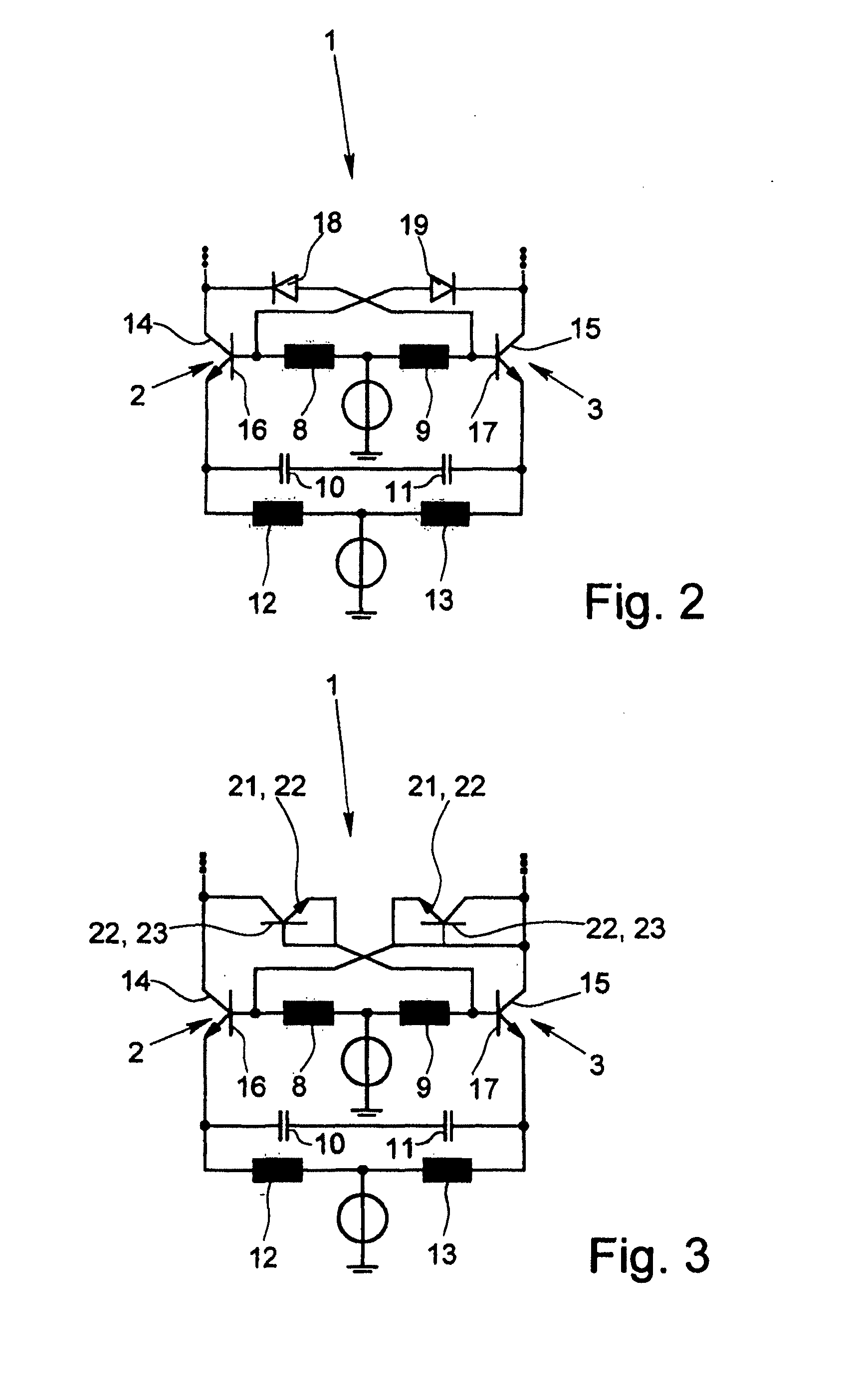
[0037]FIGS. 2 and 3 show electronic oscillators 1 belonging to circuit arrangements for creating microwave oscillations of the present invention.

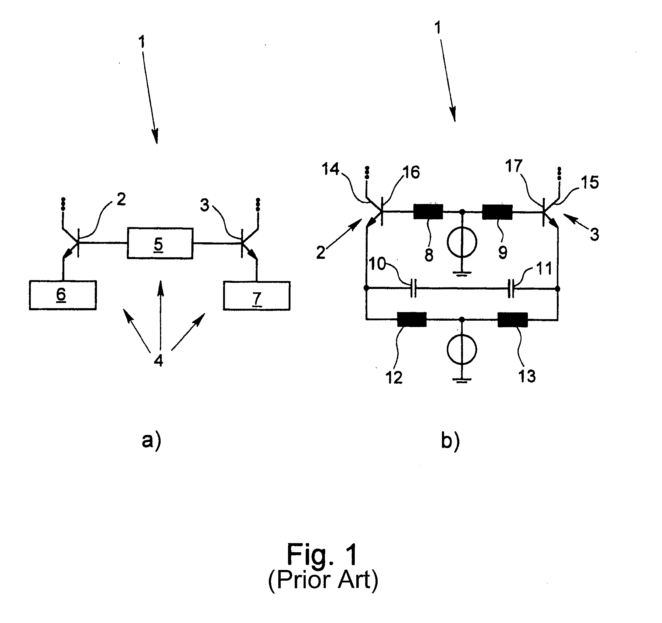
[0038]Two amplifier elements belong to each electronic oscillator 1, namely two transistors 2, 3 and a resonator 4. In the illustrated embodiments, the resonator 4 has a base impedance network 5 and two emitter impedance networks 6, 7. What is not shown is that the base impedance network 5, an emitter impedance network 6 or 7, both emitter impedance networks 6, 7 or the base impedance network 5 and the emitter impedance networks 6, 7 can be tuned. In addition to the electronic oscillator 1 shown in FIGS. 2 & 3, the electronic oscillator 1 described above and shown in FIG. 1 is referred to.

[0039]As shown in FIGS. 2 and 3, a compensation capacitance 18 or 19 is switched between the collector 14 of the first transistor 2 and the base 16 of the second transistor 3 as well as between the collector 15 of the second transistor 3 and the base 17 of...


PUM

PropertyMeasurementUnit
compensation capacitanceaaaaaaaaaa
microwaveaaaaaaaaaa

Abstract

An electronic oscillator of a circuit arrangement for creating microwave oscillations with two transistors as amplifier elements and with a resonator (4), wherein the resonator has two emitter impedance networks, the base impedance network and / or an emitter impedance network or both emitter impedance networks can be put out of tune and the transistors each have a parasitic base collector capacitance. The repercussion of the load on the electronic oscillator (“load-pulling”) is greatly reduced so as to be eliminated as much as possible, in that a compensation capacitance is switched between the collector of the first transistor and the base of the second transistor as well as between the collector of the second transistor and the base of the first transistor, and the compensation capacitances are implemented by reverse-biased pn-junctions.

Description

BACKGROUND OF THE INVENTION[0001]1. Field of the Invention[0002]The invention relates to a circuit arrangement for creating microwave oscillations having an electronic oscillator with two transistors and a resonator, preferably with a base impedance network and with two emitter impedance networks, wherein the base impedance network and / or an emitter impedance network or both emitter impedance networks can be put out of tune, wherein the transistors each have a parasitic base collector capacitance and wherein a compensation capacitance is switched between each the collector of the first transistor and the base of the second transistor as well as the collector of the second transistor and the base of the first transistor.[0003]2. Description of Related Art[0004]A circuit arrangement of the type to which this invention is directed is known from the German Patent Application 10 2008 061 254. The creation of microwave oscillations, i.e., of high frequency to highest frequency electric os...

Claims


Application Information

Patent Timeline
Patent Type & Authority Applications(United States)
IPC IPC(8): H03B5/12
CPCH03B5/1243H03B5/125H03B5/1293H03B5/1215H03B5/1231H03B5/12
Inventor POHL, NILS
Owner KROHNE MESSTECHNICK GMBH & CO KG
Why Eureka
Try Eureka