Electrolytic machining method and semifinished workpiece by the electrolytic machining method

a technology of electrolysis and machining method, which is applied in the direction of electrolysis components, manufacturing tools, transportation and packaging, etc., can solve the problems of difficulty in meeting the requirements in quality, throughput and cost, and the inability to achieve predetermined machining precision and shape, so as to reduce the problem of overlap in the machining region, improve the machining precision of the workpiece, and reduce the machining direction of the lateral machining of the machined structure.

Inactive Publication Date: 2012-07-05
METAL INDS RES & DEV CENT
View PDF3 Cites 5 Cited by
  • Summary
  • Abstract
  • Description
  • Claims
  • Application Information

AI Technical Summary

Benefits of technology

[0007]An objective of the present invention is to provide an electrolytic machining method. A metallic mask layer is disposed on the surface of a workpiece as a sacrificial layer. By the property that the electrolytic machining rate of the metallic mask layer is slower than that of the workpiece, the metallic mask layer can be used as a protective mask layer, thereby retarding width direction (lateral) machining of the machined structure. Accordingly, the shape formed on the workpiece can coincide with the predetermined one, improving machining precision of the workpiece. In addition, the method solves the problem of machining micro structures on a workpiece as well as reducing the problem of overlaps in machining regions due to small intervals while electrolytic machining, especially for the workpiece with high conductivity and high volume electrochemical equivalent.

Problems solved by technology

It would be difficult to meet the requirements in quality, throughput, and cost if traditional mechanical machining technologies are merely adopted.
Consequently, the predetermined machining precision and shape can not be achieved, especially for machining metals, such as magnesium, aluminum, copper or lithium, with high conductivity or high volume electrochemical equivalent.

Method used


Image

  • Electrolytic machining method and semifinished workpiece by the electrolytic machining method
  • Electrolytic machining method and semifinished workpiece by the electrolytic machining method
  • Electrolytic machining method and semifinished workpiece by the electrolytic machining method

Examples


Embodiment Construction

[0018]In order to make the structure and characteristics as well as the effectiveness of the present invention to be further understood and recognized, the detailed description of the present invention is provided as follows along with embodiments and accompanying figures.

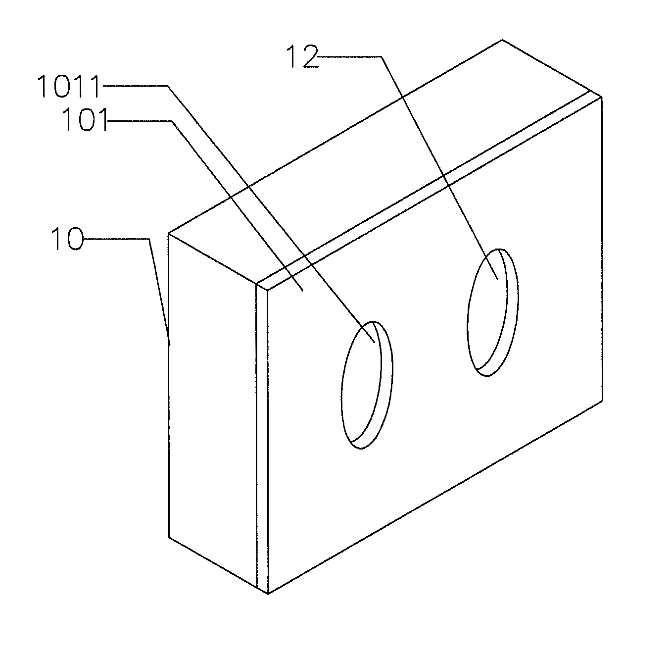
[0019]Please refer to FIGS. 3 to 7, they depict an electrolytic machining method according to the first embodiment of the present invention. For increasing size precision of electrolytic machining method, a metallic mask layer is formed on the surface of a workpiece whose material specially has high conductivity or volume electrochemical equivalent, whereby the metallic mask layer can be used as a sacrificial layer of electrolytic machining and simultaneously protects the non-machining region of the workpiece so as to reduce lateral machining of the workpiece. Consequently, the size precision of electrolytic machining is enhanced. In addition, the feasibility of electrolytically machining a miniature interval betwe...


PUM

PropertyMeasurementUnit
thicknessaaaaaaaaaa
thicknessaaaaaaaaaa
thicknessaaaaaaaaaa

Abstract

The present invention relates to an electrolytic machining method. For increasing size precision of electrolytic machining method, a metallic mask layer is formed on the surface of a workpiece whose material has high conductivity or volume electrochemical equivalent, whereby the metallic mask layer can be used as a sacrificial layer of electrolytic machining and simultaneously protects the non-machining region of the workpiece so as to reduce lateral machining of the workpiece Consequently, the size precision of electrolytic machining is enhanced. In addition, the feasibility of electrolytically machining a miniature interval between two machined structures is increased as well. In addition, the present invention provides a semifinished electrolytic workpiece, comprising a workpiece and a metallic mask layer formed on the surface of the workpiece. The conductivity or volume electrochemical equivalent of the metallic mask layer is smaller than that of the workpiece.

Description

[0001]This application claims the priority benefit of Taiwan Patent Application Ser. No. 099146789 on Dec. 30, 2010, the full disclosure of which is incorporated herein by reference.FIELD OF THE INVENTION[0002]The present invention relates generally to an electrolytic machining method, and particularly to an electrolytic machining method capable of enhancing size precision.BACKGROUND OF THE INVENTION[0003]In recent years, in addition to improving varieties in functionality, 3C, biomedical, and emerging energy products also feature smaller size and lighter weight as well as emphasize precision and quality of products. The capable requirements in size and quality of machining product parts are greater accordingly. Besides, the characteristics of applied materials, such as hardness and elongation, also tend to varieties. It would be difficult to meet the requirements in quality, throughput, and cost if traditional mechanical machining technologies are merely adopted.[0004]Currently, a ...

Claims


Application Information

Patent Timeline
Patent Type & Authority Applications(United States)
IPC IPC(8): B32B15/01B32B3/00B23H3/00
CPCY10T428/12389C25F3/14
Inventor HUNG, JUNG-CHOULIN, DA-YU
Owner METAL INDS RES & DEV CENT
Why Eureka
Try Eureka