
Temperature measuring device

a temperature measurement and device technology, applied in the field of tracheal temperature measurement devices, can solve the problems of up to 25% fatalities, and achieve the effects of less time-consuming, improved patient outcomes, and more accurate monitoring methods

Inactive Publication Date: 2012-07-05
DUNN LISA A
View PDF24 Cites 2 Cited by
  • Summary
  • Abstract
  • Description
  • Claims
  • Application Information

AI Technical Summary

Benefits of technology

[0026]Additionally, the apparatus of the invention can effectively be used for patients on ECMO (extra corporeal membrane oxygenation) that require close monitoring and in situations where the patient exhibits respiratory distress, weak or diseased heart or lungs that require artificial means of removing carbon monoxide from their lungs and exchanging it for oxygenated blood through a mechanical filter hooked up via large veins by an intravenous catheter (tube). In this latter instance, it has long been recognized that these vein puncture access sites are a source of infection and lead to sepsis resulting in up to 25% fatalities. By having a less time consuming and more accurate way to monitor the temperatures of these patients, infections could be detected earlier and patient outcomes would be improved.
[0027]In light of the foregoing, it is an object of the present invention to provide an apparatus for accurately measuring the body temperature of a patient at the tracheal wall of the patient.
[0028]Another object of the invention is to provide an apparatus of the aforementioned character that is self-contained and does not have to be interconnected with expensive monitoring equipment.
[0031]Another object of the invention is to provide an apparatus of the class described that includes a novel handheld temperature readout assembly that is easy to use by the caregiver and one which clearly and accurately displays the temperature of the patient. More particularly, it is an object of the invention to provide such an apparatus in which the handheld temperature readout assembly includes a handheld housing having a viewing window and a light emitting diode temperature display that is carried by the housing and is readily viewable through the viewing window of the handheld housing for displaying the patient temperature.

Problems solved by technology

In this latter instance, it has long been recognized that these vein puncture access sites are a source of infection and lead to sepsis resulting in up to 25% fatalities.

Method used


Image

  • Temperature measuring device
  • Temperature measuring device
  • Temperature measuring device

Examples


Embodiment Construction

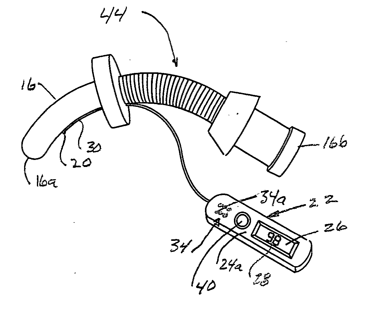
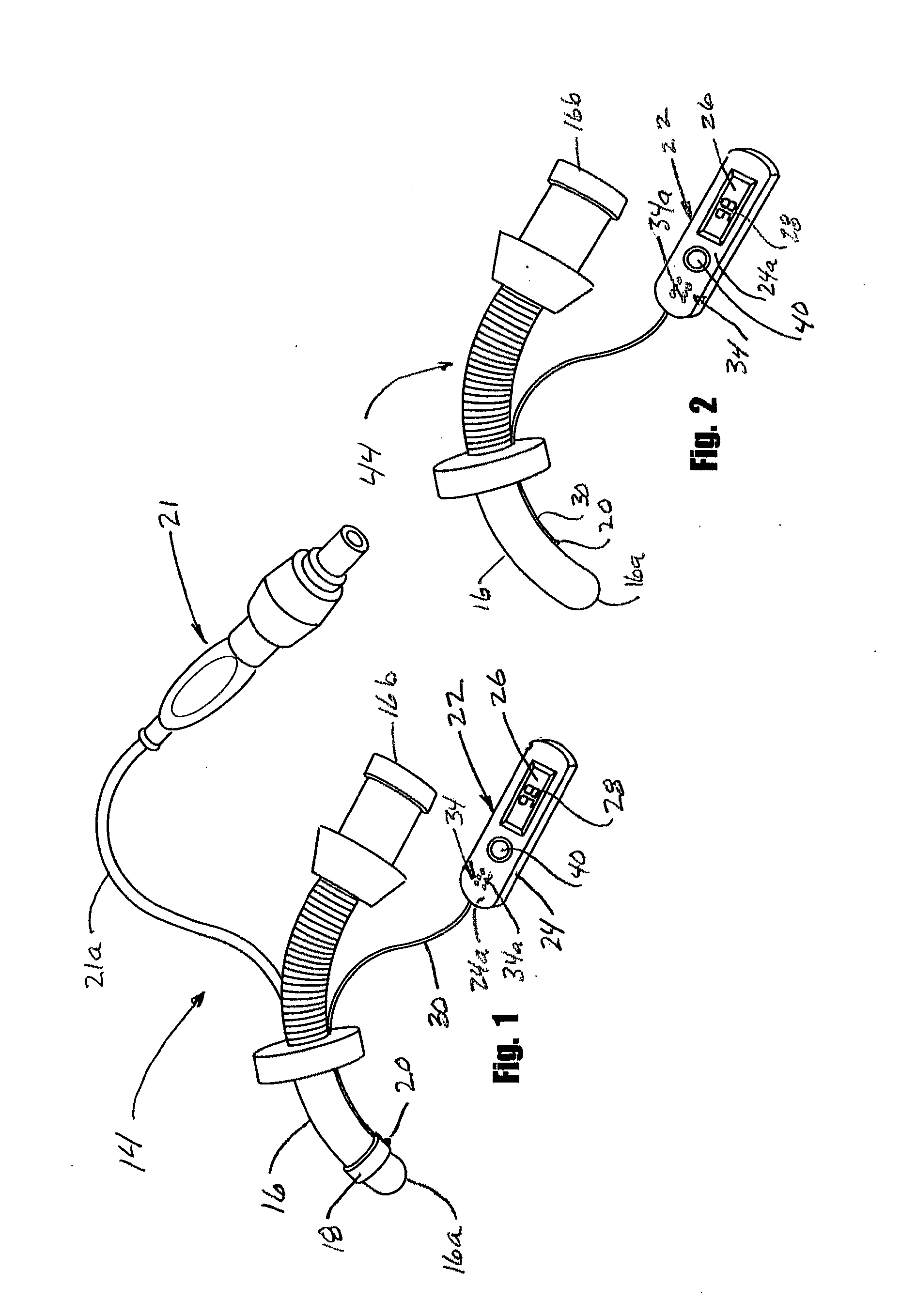
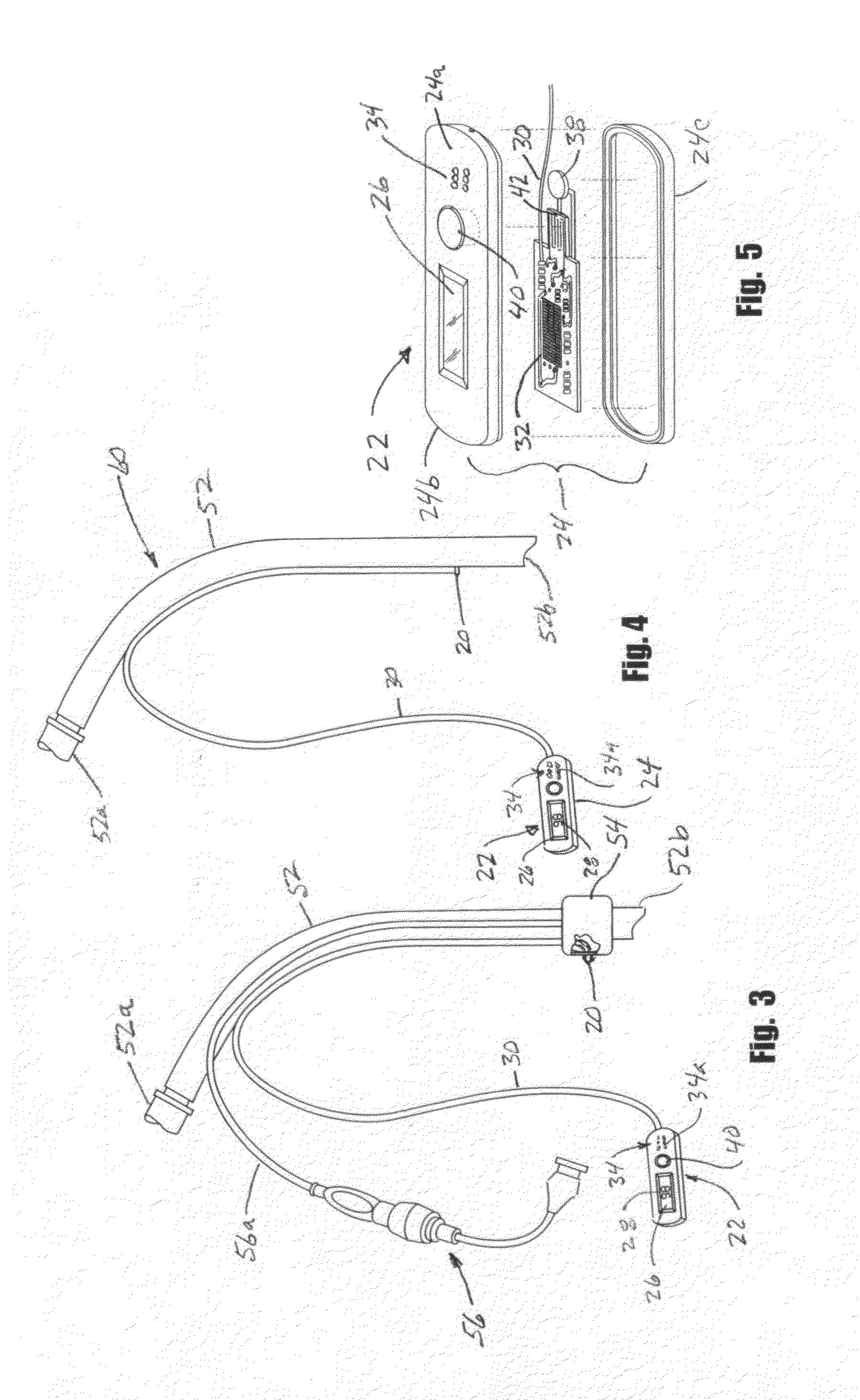
[0039]Referring to the drawings and particularly to FIGS. 1 and 5, one form of the temperature measuring apparatus of the invention for measuring the temperature of the patient is there illustrated and generally designated by the numeral 14. This form of the apparatus here comprises a tracheostomy tube 16 that has a curved interior end portion 16a and an exterior end 16b. The interior end 16a of the tube is constructed and arranged to enter the trachea of the patient via a tracheostomy stoma in a conventional manner well understood by those skilled in the art. Provided on the interior end portion 16a of the tube is a conventional, inflatable cuff 18 that is so constructed and arranged as to engage the wall of the trachea of the patient when inflated. As illustrated in FIG. 1 of the drawings, a temperature sensor 20 in the form of a temperature-responsive element is connected to the inflatable cuff 18 and is arranged to engage the trachea wall of the patient when the tube is in posit...


PUM


Abstract

An apparatus for accurately measuring the body temperature of a patient at the tracheal wall of the patient. The apparatus includes a novel handheld temperature readout assembly that is easy to use by the caregiver and one which clearly and accurately displays the temperature of the patient. The handheld temperature readout assembly includes a handheld housing having a viewing window and a light emitting diode temperature display that is carried by the housing and is readily viewable through the viewing window of the handheld housing for displaying the patient temperature. The apparatus also includes a built-in alarm system to alert to high and low body temperatures.

Description

CROSS-REFERENCE TO RELATED APPLICATIONS[0001]Not ApplicableSTATEMENT REGARDING FEDERALLY SPONSORED RESEARCH OR DEVELOPMENT[0002]Not ApplicableINCORPORATION-BY-REFERENCE OF MATERIAL SUBMITTED ON A COMPACT DISC[0003]Not ApplicableBACKGROUND OF THE INVENTION[0004]1. Field of the Invention[0005]The present invention relates generally to apparatus for measuring body temperature. More particularly, the invention concerns an apparatus for measuring tracheal temperatures.[0006]2. Description of Related Art Including Information Disclosed Under 37 CFR 1.97 and 1.98[0007]A number of different types of temperature measuring apparatus using various types of temperature sensing devices such as thermisters, thermocouples and resistance temperature sensors have been suggested in the past. Typically, the prior art temperature sensing devices are placed under the arm, in the ear or in the rectum. Additionally, temperature is sometimes measured by temporal scanning techniques.[0008]Special problems e...

Claims


Application Information

Patent Timeline
Patent Type & Authority Applications(United States)
IPC IPC(8): A61B5/01
CPCA61B5/01A61B5/08A61B5/6852A61B2503/045G01K13/002A61M16/0465A61M2205/18A61M2205/502A61M2230/50A61M16/04G01K13/20
Inventor DUNN, LISA A.
Owner DUNN LISA A
Learn More