
Power tool

a technology of power tools and motors, applied in the field of power tools, can solve the problems of shortening the life of the motor, not providing for the ability to operate the drill in anything other than a high speed mode,

Inactive Publication Date: 2012-07-12
DEMAIN TECH
View PDF5 Cites 16 Cited by
  • Summary
  • Abstract
  • Description
  • Claims
  • Application Information

AI Technical Summary

Benefits of technology

[0010]The invention is advantageous in that it provides a power tool, such as a power drill, which incorporates an alternating current powered motor which can drive rotation of the driven member, or chuck, at speeds that are higher than those achievable by direct current motor driven power tools. The power tool also includes a driven member, or chuck, which can be adjusted to grip and release a working element without requiring manual adjustment of the driven member such as by way of a chuck release tool. The invention is also advantageous in that it provides at least two speed settings, such as high and low speed settings, whereby the driven member, or chuck, is capable of being driven at two different speeds relative to a given speed of rotation of the motor. Furthermore, by providing a torque controller which is capable of controlling the amount of torque supplied by the motor to the driven member the invention is advantageous over power tools which offer only direct driving engagement from the motor to the driven member. By providing a torque controller the invention can avoid breakage of components or of working elements and can extend the life of the motor by ameliorating instances in which the armature within the motor comes to a standstill. The torque controller is also advantageous for screw driving and bolt or nut tightening as it facilitates control of the amount of torque applied to a screw, bolt or nut. Controlling the amount of torque applied to a screw, bolt or nut helps facilitate control of the depth to which a screw is screwed into a workpiece, helps to avoid splitting the workpiece and stripping of the nut or bolt.
[0047]In one form, the power tool further includes a manual adjustment device for adjusting the pre-determined level of torque between a plurality of settings wherein at least one setting facilitates adjustment of the driven member by the switch to the adjustment mode and at least one setting prevents adjustment of the driven member by the switch to the adjustment mode and maintains the driven member in the drive mode.

Problems solved by technology

Such power tools also can include only a single speed transmission assembly which does not provide for the ability to operate the drill in anything other than a high speed mode.
Furthermore, such power tools can also involve direct driving engagement from the motor to the driven member such that if the driven member becomes jammed as a result of the working element becoming jammed in a work piece the resulting force transferred the power tool can result in either the power tool coming out of a user's hands, breaking the working element or breaking part of the transmission assembly joining the motor to the driven member or otherwise can result in the armature within the motor coming to a standstill which can result in the motor burning out or at least can result in shortening the life of the motor.

Method used


Image

  • Power tool
  • Power tool
  • Power tool

Examples


Embodiment Construction

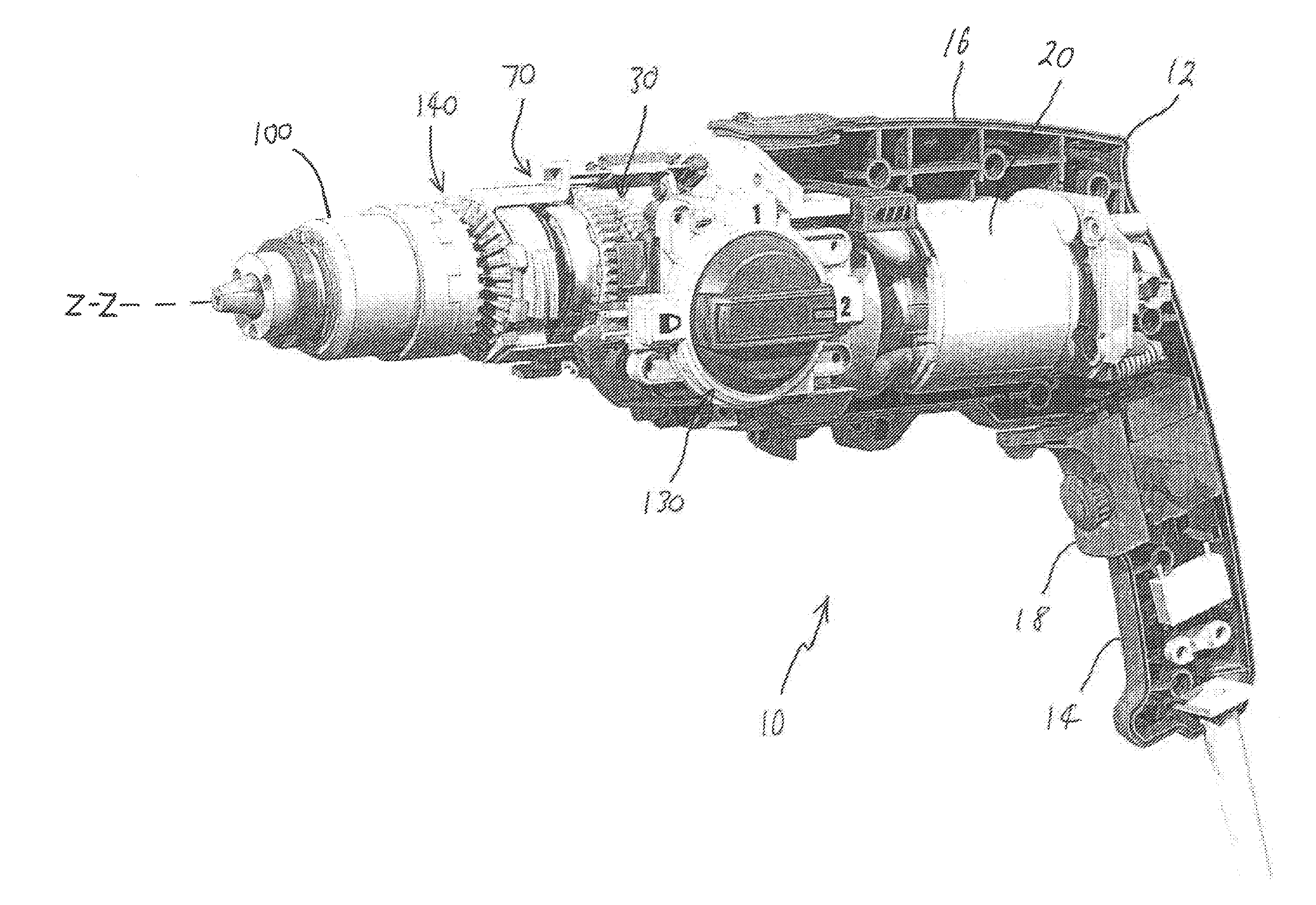
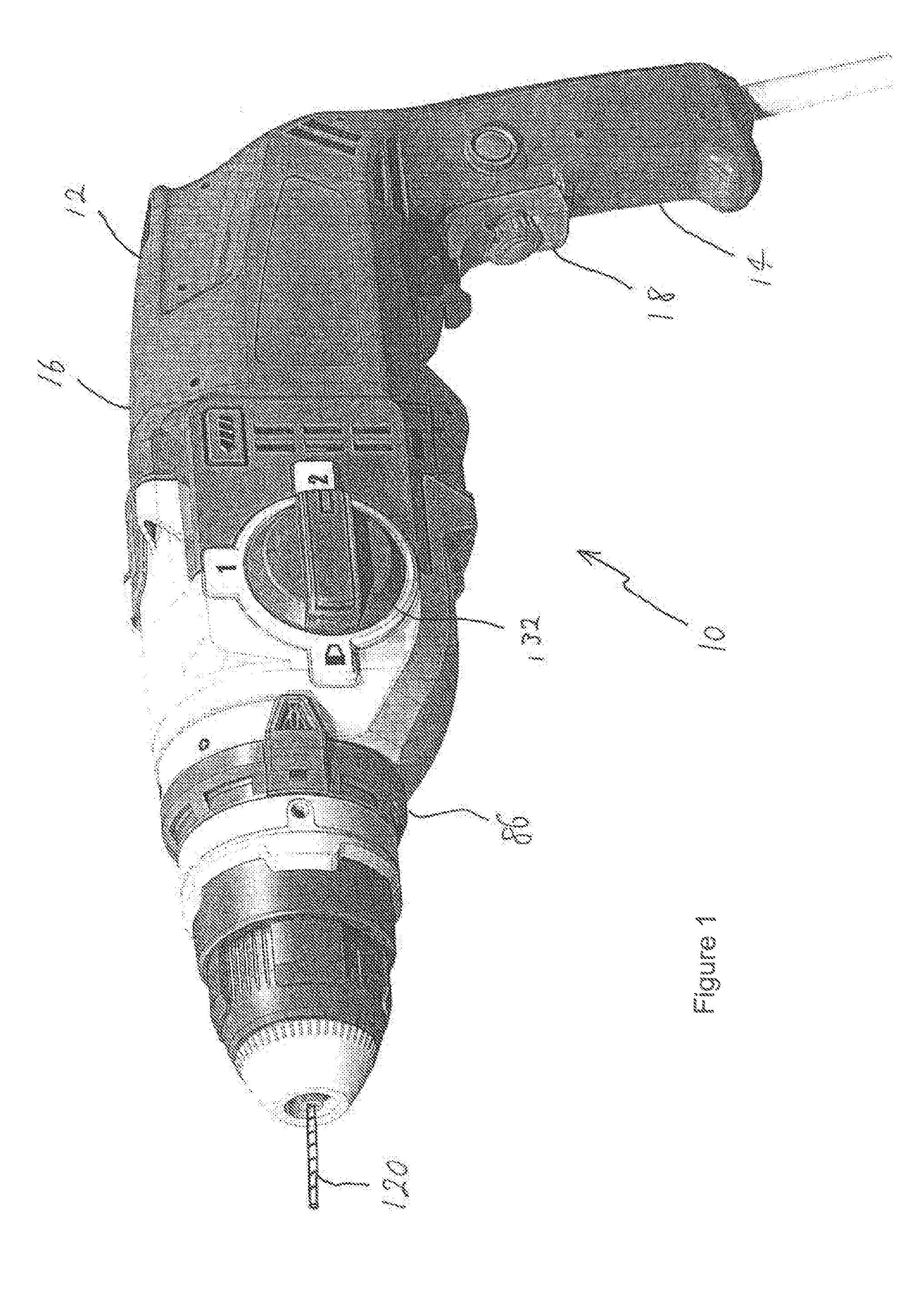
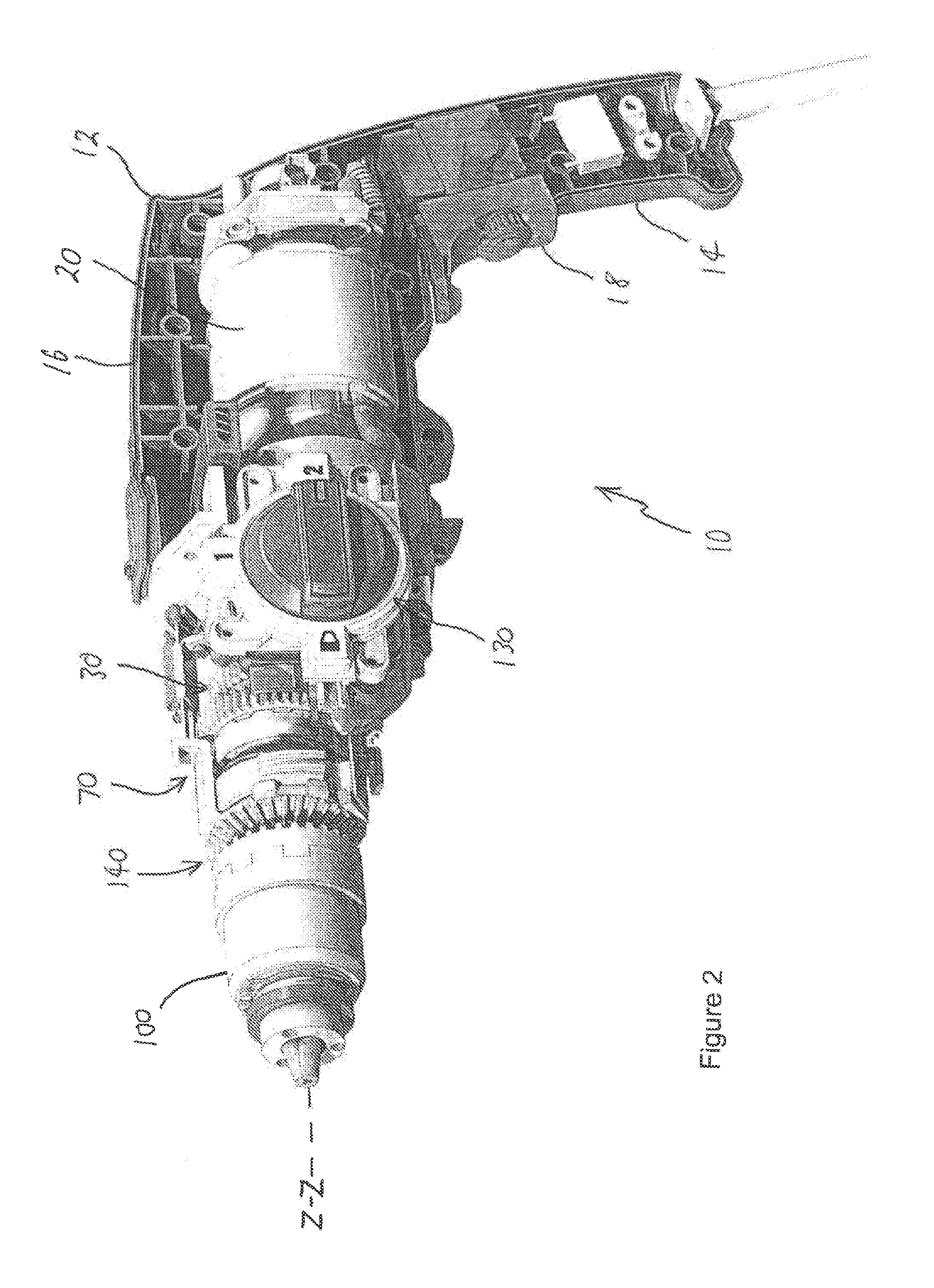
[0099]Referring to FIGS. 1 and 2, there is shown a power tool 10 which, in the particular embodiment illustrated, is in the form of a power drill. The power tool 10 includes a housing 12 which contains internal components of the power tool 10. The housing 12 includes a handle portion 14 which is configured for being gripped by a user. The handle 14 is connected to the main body 16 of the housing 12. The body 16 houses a motor 20 which, in a particularly preferred form, is an alternating current powered motor. The motor 20 includes a rotating armature (not shown) which has a portion which protrudes from a forward portion of the motor 20. A helical input gear (not shown) is fixed to the protruding portion of the armature. When the trigger 18 is operated alternating current is supplied from a power source to the motor 20 such that the armature is caused to rotate which in turn causes the helical input gear 27 to also rotate.

[0100]Referring to FIG. 2, the power tool 10 includes a rotata...


PUM

PropertyMeasurementUnit
Speedaaaaaaaaaa
Torqueaaaaaaaaaa

Abstract

The invention provides a transmission assembly and a power tool. One form of the power tool includes a rotatable driven member for releasably gripping and rotating a working element and a transmission assembly for transmitting rotation from a motor to the driven member. The transmission assembly includes a rotatable input shaft and first and second rotatable output shafts. In a first speed setting the input shaft is selectively lockable together with the first output shaft so that the locked input shaft and first output shaft rotate in unison to drive rotation of the driven member at a first speed of rotation relative to a speed of rotation of the motor. In a second speed setting the input shaft is selectively lockable to the second output shaft so that the locked input shaft and second output shaft rotate in unison to drive rotation of the driven member at a second speed of rotation relative to the speed of rotation of the motor. Another form includes a torque controller operable for controlling torque supplied from the motor to the driven member to render the driven member stationary when the amount of torque supplied from the motor to the driven member exceeds a pre-determined level. Another form includes a switch mechanism for adjusting the transmission assembly between the first and second speed settings and for rendering the torque controller operable or inoperable. Another form includes a torque controller for use with a power tool and operable for controlling torque transmitted from an input shaft to an output shaft.

Description

FIELD OF THE INVENTION[0001]The present invention relates to the field of power tools. The present invention has particular application in respect of power drills and in particular power drills including a motor powered by alternating current. However, it is to be appreciated that the present invention may have broader application than in respect of such power tools.BACKGROUND OF THE INVENTION[0002]The existing power drills incorporating a motor powered by alternating current are typically used in applications where high speed operation of a working element is required such as for drilling through masonry and other hard work pieces. Such power drills typically incorporate a rotatable driven member in the form of a chuck which incorporates a set of gripping jaws for releasably gripping and holding a working element such as a drill bit. The driven member is operably coupled to the alternating current powered motor such that when the power tool is activated the motor drives rotation of...

Claims


Application Information

Patent Timeline
IPC IPC(8): B23B45/16B25F5/00B23B47/14
CPCB23B45/008B23B2260/0445F16D7/025B25F5/001B25B23/141
Inventor VAN DER LINDE, BENJAMIN L.CONNOR, PAUL F.
Owner DEMAIN TECH
Learn More