Vacuum Switch With Pre-Insertion Contact

a vacuum switch and contact technology, applied in the direction of contact mechanisms, air-break switches, high-tension/heavy-dress switches, etc., can solve the problems of complex and costly external switching techniques, environmental concerns, stress or damage to equipment connected to the circuit, etc., and achieve the effect of high energy dissipation

Active Publication Date: 2012-07-12
GLASER MICHAEL DAVID
View PDF4 Cites 19 Cited by
  • Summary
  • Abstract
  • Description
  • Claims
  • Application Information

AI Technical Summary

Benefits of technology

[0011]Accordingly, it is the principal object of the present invention to provide a single vacuum switch module with pre-insertion contacts activated by the motion of the main contacts and a resistor or inductor arrangement that effectively limits transient in-rush currents and / or voltages during operation of the device and does not require high energy dissipation, complex mechanical or electronic switching systems or precise insertion timing.

Problems solved by technology

Such transient current and / or voltages can produce undesirable noise both audible and electrical and can, of course, also lead to distress or damage to equipment connected to the circuit.
The vacuum devices of this type rely on complex and costly external switching techniques, while the non-vacuum devices rely on an air switch, which is quite noisy and bulky or SF6 devices, which are now creating environmental concerns due to the affect of escaped SF6 gas on the ozone layer.
However, such an arrangement does have its drawbacks since the inductor must be designed to carry continuous load currents and fault currents.
In addition, there are ongoing costs associated with power losses in the inductor on a continuous basis as well as a reduction in the effectiveness of the capacitor bank to which it is connected.
This results in an arrangement that is complex and costly.
The combination of the two interrupters results in a switching device, which is also complex, costly and has the aforementioned environmental concerns associated with SF6 gas.
This type of vacuum switch is quite complex and costly, and can be difficult to set up when utilized in three phase applications.
This configuration is suitable for providing a means to ground the electric circuit in which the vacuum switch or interrupter is employed, but because the contact means is not capable of engaging both sets of contacts by moving in one direction, the vacuum interrupters do not provide a pre-insertion means.
While work hardening will result in the return of some of the spring force characteristics, its final force characteristics will be uncontrolled.
Additionally, this device is not suitable as a pre-insertion device as no means is provided to precisely position the driven contact or to adjust out the tolerance accumulation between the multiple parts.

Method used


Image

  • Vacuum Switch With Pre-Insertion Contact
  • Vacuum Switch With Pre-Insertion Contact
  • Vacuum Switch With Pre-Insertion Contact

Examples


Embodiment Construction

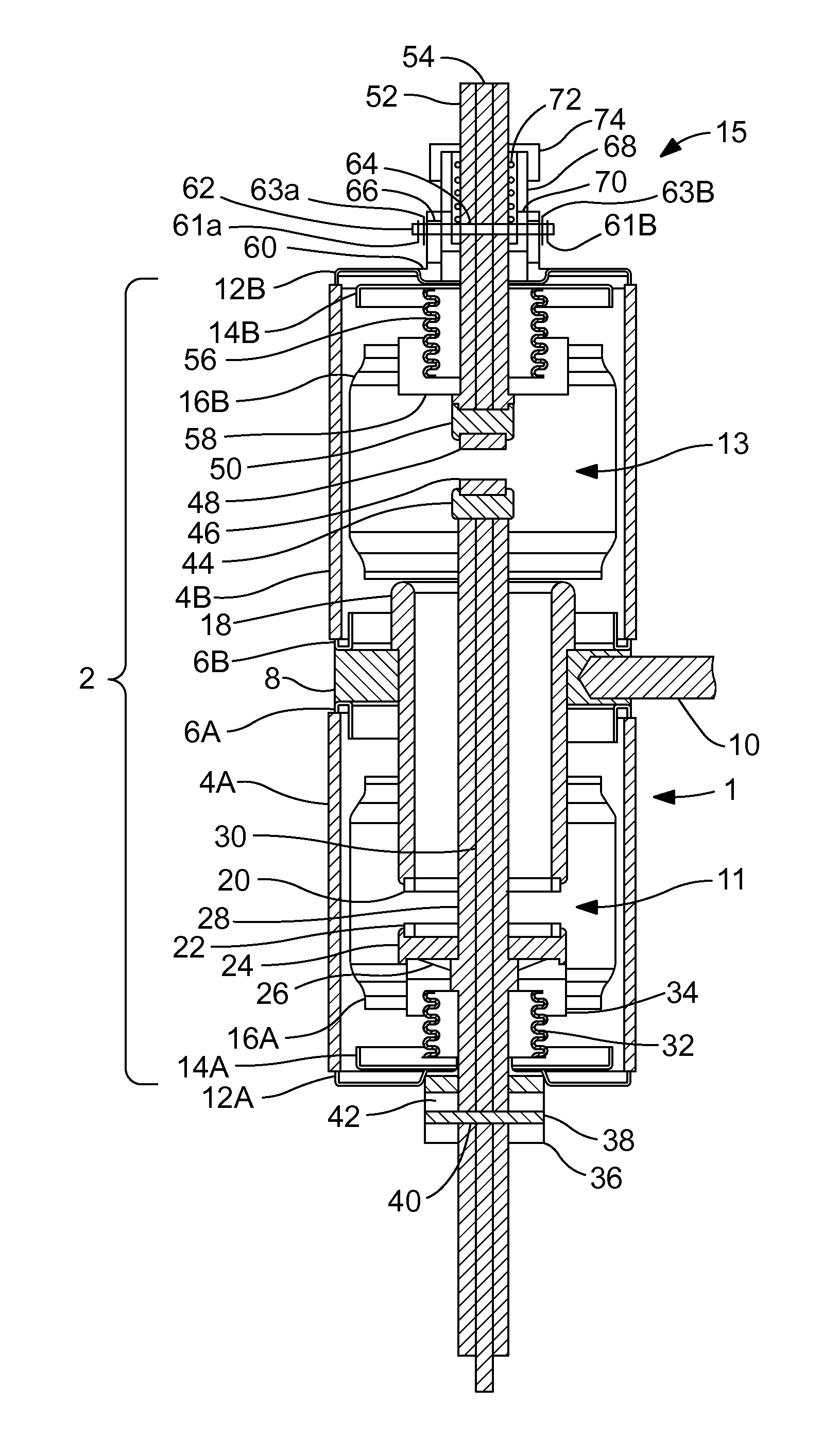
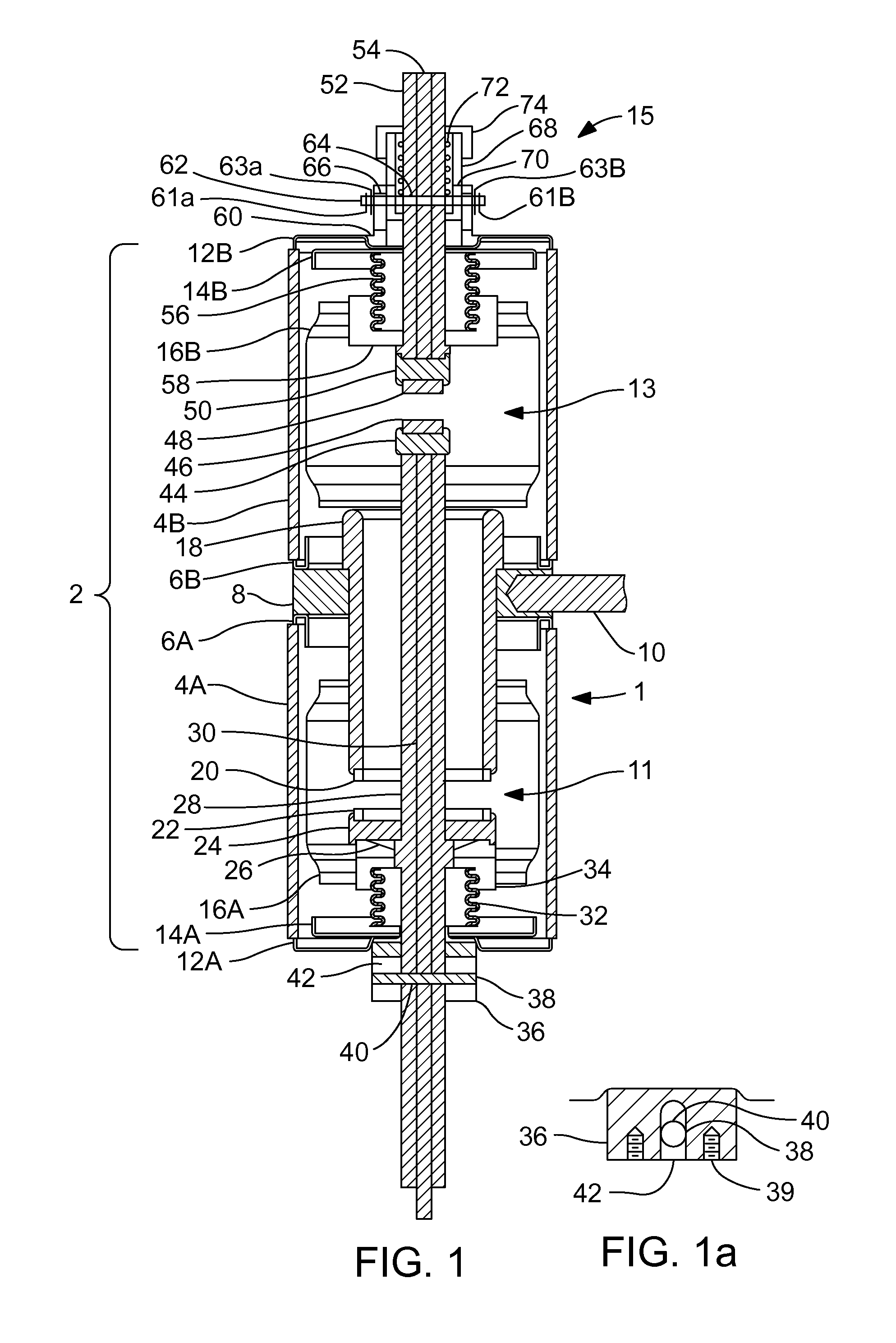
[0022]FIG. 1 discloses a vacuum switch with pre-insertion contact (vacuum switch) 1. The vacuum switch 1 includes a vacuum envelope 2. The major part of the vacuum envelope 2 includes a pair of insulating cylinders 4A and 4B preferably fabricated from alumina ceramic and joined end-to-end by way of two stainless steel or monel triple point shields 6A and 6B and a stationary contact support ring 8 preferably fabricated from copper. A threaded hole in the stationary contact support ring 8 allows the attachment of a terminal rod 10 preferably fabricated from copper to facilitate electrical connection to the load line. The opposite ends of the ceramic cylinders are enclosed by two end cups 12A and 12B preferably fabricated from stainless steel or monel.

[0023]A second set of triple point shields 14A and 14B preferably fabricated from stainless steel or monel are attached to the end cups 12A and 12B. A generally tubular internal shield 16A and 16B is provided within each insulating cylind...


PUM


Abstract

A vacuum switching device with pre-insertion contact arrangement is disclosed. The vacuum switch includes first and second contact systems. The first contact system includes an annular stationary contact and an annular moving contact retained on a moving contact drive rod. A second contact system includes a moving contact retained on an end of the moving contact drive rod and a floating contact retained along the same axis as the second moving contact. Both contact systems are enclosed in a vacuum envelope. A mechanical adjustment system is provided for the floating contact, which allows it to be positioned so that the secondary moving contact and floating moving contact may engage at a set interval before the annular moving contact engages the annular stationary contact. A resistor or inductor is connected between the second contact system and a load to prevent a current in-rush into the load.

Description

BACKGROUND OF THE INVENTION[0001]1. Field of the Invention[0002]The present invention relates to the field of high voltage vacuum switches and circuit interrupting devices and more particularly to a vacuum switch with a pre-insertion resistor or inductor arrangement to limit transient in-rush currents and or voltage transients during the closing and opening of a power distribution circuit containing capacitor banks.[0003]2. Discussion of the Prior Art[0004]A number of vacuum and non-vacuum prior art arrangements are directed to pre-insertion resistors or inductors for circuit interrupting devices wherein a resistor or inductor is either inserted in series with a high voltage switch or in parallel with a switch gap during the closing movement of the switch or interrupting unit to reduce audible and electrical noise and to limit transient in-rush current and / or voltages incident to completion of the circuit by the switch or interrupting unit. For example pre-insertion resistors of thi...

Claims


Application Information

Patent Timeline
Patent Type & Authority Applications(United States)
IPC IPC(8): H01H33/66
CPCH01H33/166H01H2003/323H01H33/6647
Inventor GLASER, MICHAEL DAVID
Owner GLASER MICHAEL DAVID
Why Eureka
Try Eureka