
Electrical panel heating device and method and building materials for the protection thereof

Active Publication Date: 2012-07-12
ZIMMERER WILHELM +1
View PDF4 Cites 11 Cited by
  • Summary
  • Abstract
  • Description
  • Claims
  • Application Information

AI Technical Summary

Benefits of technology

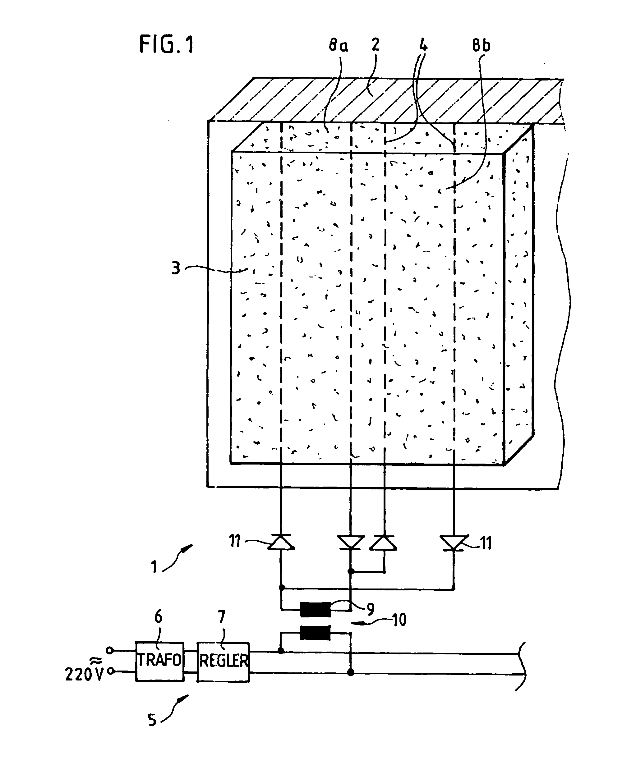
[0018]The aim of creating the most uniform possible sheet-shaped current is served by a refinement of the invention according to which an electrical panel heating device that is brought to final form by the curing of an initially liquid or pasty building material is further provided with contacts for injecting a sheet current. Generally, the flow of current is in the direction of this sheet; however, it would also be conceivable in the context of the invention to provide a current flow that runs obliquely or even perpendicularly to the particular sheet. The direction of current flow is dictated here by the arrangement of the contacts. For current flow within the sheet, both contacts must also be disposed within the sheet concerned; for current flow approximately perpendicular thereto, the two contacts must be offset from each other approximately perpendicularly to the sheet concerned. Alternatively, however, the contact strips can taper or flare continuously instead of extending parallel to each other. A stronger or less strong current flow is developed as a function of this choice, with the result that higher or lower heat production per unit area occurs at the locations concerned.
[0020]The building material according to the invention preferably contains inert additives, for example sand or rock flour. The primary purpose of such additives is to reduce the proportion of binder matrix, thus eliminating excessive costs.
[0021]In addition, the building material according to the invention can also be admixed with functional additives, for example cellulose, fibers, etc. In contrast to the inert additives cited above, additives of this kind are intended to perform certain functions, for example to increase strength, as in the case of fiber reinforcement; to lower thermal conductivity, for example by means of air entraining agents or lightweight additives; to reduce mechanical vibration, for example, with the aid of heavyweight additives; and furthermore to improve density and / or watertightness, strength, workability and / or workability time, etc.
[0043]The heating device is advantageously arranged to be connected for operation to a low voltage of up to 60 V. A low voltage of around 12 V to 48 V is particularly preferable. If, for example, the heating device is to be connected to a mains voltage, e.g., to a 230 V a.c. voltage, then it is useful to interpose an (isolating) transformer that galvanically isolates the heating device from the supplying network. Due to the use of a low voltage, even direct contact with the heating device connected to a low-voltage source is non-hazardous.
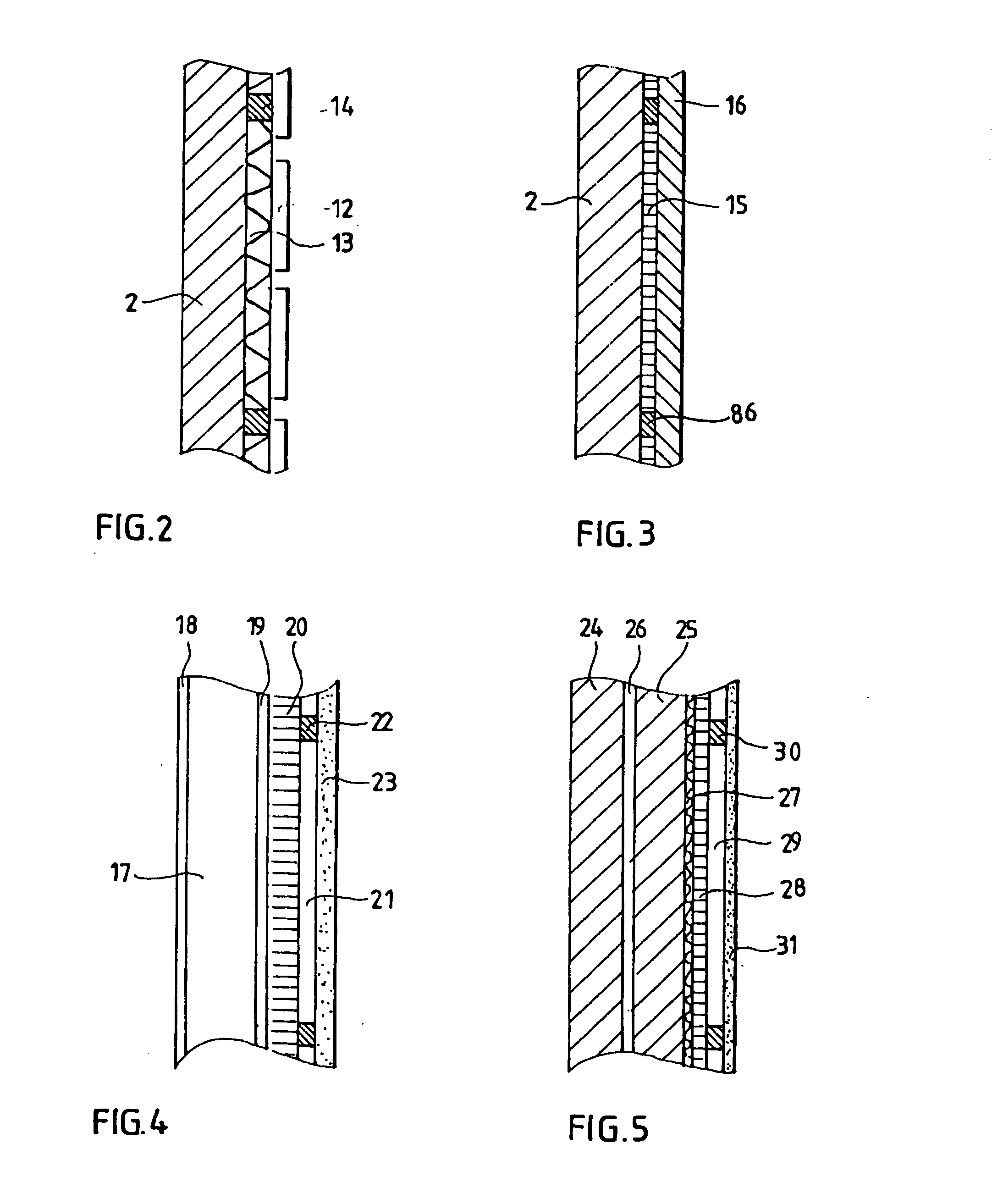
[0046]Under these circumstances, a distance of approximately 1.0 mm to 20 mm between the heating device and the wall or ceiling is advantageous. Particularly preferred is a distance of 2.0 mm to 10 mm, particularly 3.0 mm to 8.0 mm, between the heating device and the wall or ceiling. Distances of more than 20 mm are also conceivable, of course. But it should be kept in mind that the space between the heating device and the wall or ceiling normally represents lost useful area, so overly large distances should generally be avoided.

Problems solved by technology

In many buildings, particularly old structures with high-ceilinged rooms, it is often difficult to heat a room to a comfortable temperature, since, especially in southern climes, either there is no heating system at all, or the one that is present is not adequate for cold winter days.
Known heating systems usually are high-priced, are complicated to install and sometimes entail structural modifications.
Known panel heating devices are designed, for example, to be disposed under the plaster of a wall and are unsuitable for retrofitting in a finished building.

Method used


Image

  • Electrical panel heating device and method and building materials for the protection thereof
  • Electrical panel heating device and method and building materials for the protection thereof
  • Electrical panel heating device and method and building materials for the protection thereof

Examples


Embodiment Construction

[0066]FIG. 1 is a schematically and greatly simplified drawing of one embodiment of a heating device 1 according to the invention. Disposed on and / or at a solid, load-bearing-capable substrate 2 is a heating layer 3 composed of a cured building material according to the invention. The heating layer 3 preferably has a smaller thickness d than the load-bearing-capable substrate 2, for example a thickness d of between 1 mm and 10 mm, and, by virtue of conductive particles mixed into an inorganic binder matrix, its electrical resistivity ρ is lower than the specific electrical conductivity ρ of the substrate material 2, for example at least twice as high, preferably at least twenty times higher, particularly at least two hundred times higher.

[0067]Extending at or in the conductive heating layer 3 are two or more electrically conductive contacts 4. These contacts 4 can, for example, be constituted by copper tracks or copper wires, which preferably run parallel to one another, particularl...


PUM

PropertyMeasurementUnit
Distanceaaaaaaaaaa
Distanceaaaaaaaaaa
Electrical conductivityaaaaaaaaaa

Abstract

The invention relates to an electrical panel heating device and to a method and a material for the production thereof; the panel heating device is produced by curing a liquid or pasty material, comprising at least one inorganic binding agent, for example cement and / or gypsum, at least one electrically non-conductive additive, for example sand and / or rock flour, and at least one further additive composed of electrically conductive particles, for example carbon fibres and / or trips; after mixing this material in the liquid or pasty state, it is processed to form a product in the form of a panel which is provided with low-impedance contacts for feeding in a current distributed over an panel.

Description

BACKGROUND OF THE INVENTION[0001]1. Field of the Invention[0002]This invention is directed to an electrical panel heating device and to a method and a building material for the production thereof.[0003]2. Description of the Prior Art[0004]In many buildings, particularly old structures with high-ceilinged rooms, it is often difficult to heat a room to a comfortable temperature, since, especially in southern climes, either there is no heating system at all, or the one that is present is not adequate for cold winter days.[0005]Known heating systems usually are high-priced, are complicated to install and sometimes entail structural modifications. Known panel heating devices are designed, for example, to be disposed under the plaster of a wall and are unsuitable for retrofitting in a finished building.[0006]In addition, many electrical heating devices contain water- or vapor-impermeable films or layers, between which the heating device per se is located. Such heaters prevent the necessar...

Claims


Application Information

Patent Timeline
IPC IPC(8): H05B3/00H01B1/18H01B1/16
CPCF24D13/022H05B3/141H05B3/24Y10T29/49083H05B2203/017H05B2203/026Y02B30/26H05B2203/011Y02B30/00
Inventor ZIMMERER, WILHELMZIMMERER, LAURA
Owner ZIMMERER WILHELM
Learn More