Pipe joining device

a pipe joining and pipe technology, applied in the direction of branching pipes, service pipes, drawing-off water installations, etc., can solve the problems of resin having a finite shelf life, corrosion due to corrosion becoming an increasing problem, and expensive and time-consuming to dig down to underground pipes to make pipe repairs, etc., to improve the quality of welds.

Inactive Publication Date: 2012-07-12
EPL COMPOSITE SOLUTIONS LTD
View PDF18 Cites 15 Cited by
  • Summary
  • Abstract
  • Description
  • Claims
  • Application Information

AI Technical Summary

Benefits of technology

[0016]Preferably, the flange portion tapers in thickness as it extends outwardly from the tubular portion. This is advantageous as it improves the quality of a weld between the first pipe sealing portion and the first pipe as the taper ensures a close contact between the first pipe and the first pipe sealing portion

Problems solved by technology

Pipes used for mains water supplies are often made of cast iron, and failure due to corrosion is becoming an increasing problem as existing systems age.
It is very expensive and time consuming to dig down to underground pipes to make repairs to pipes, particularly between main pipes and branch pipes.
The resin has a finite shelf life, particularly at high ambient temperatures.
When the resin is applied

Method used


Image

  • Pipe joining device
  • Pipe joining device
  • Pipe joining device

Examples


first embodiment

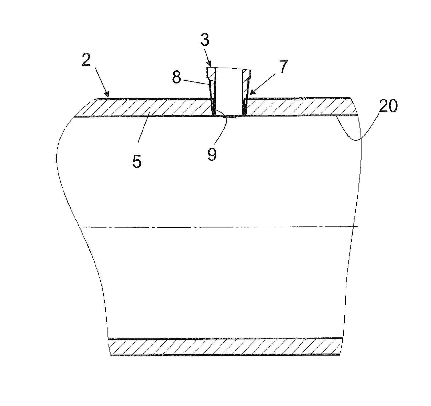
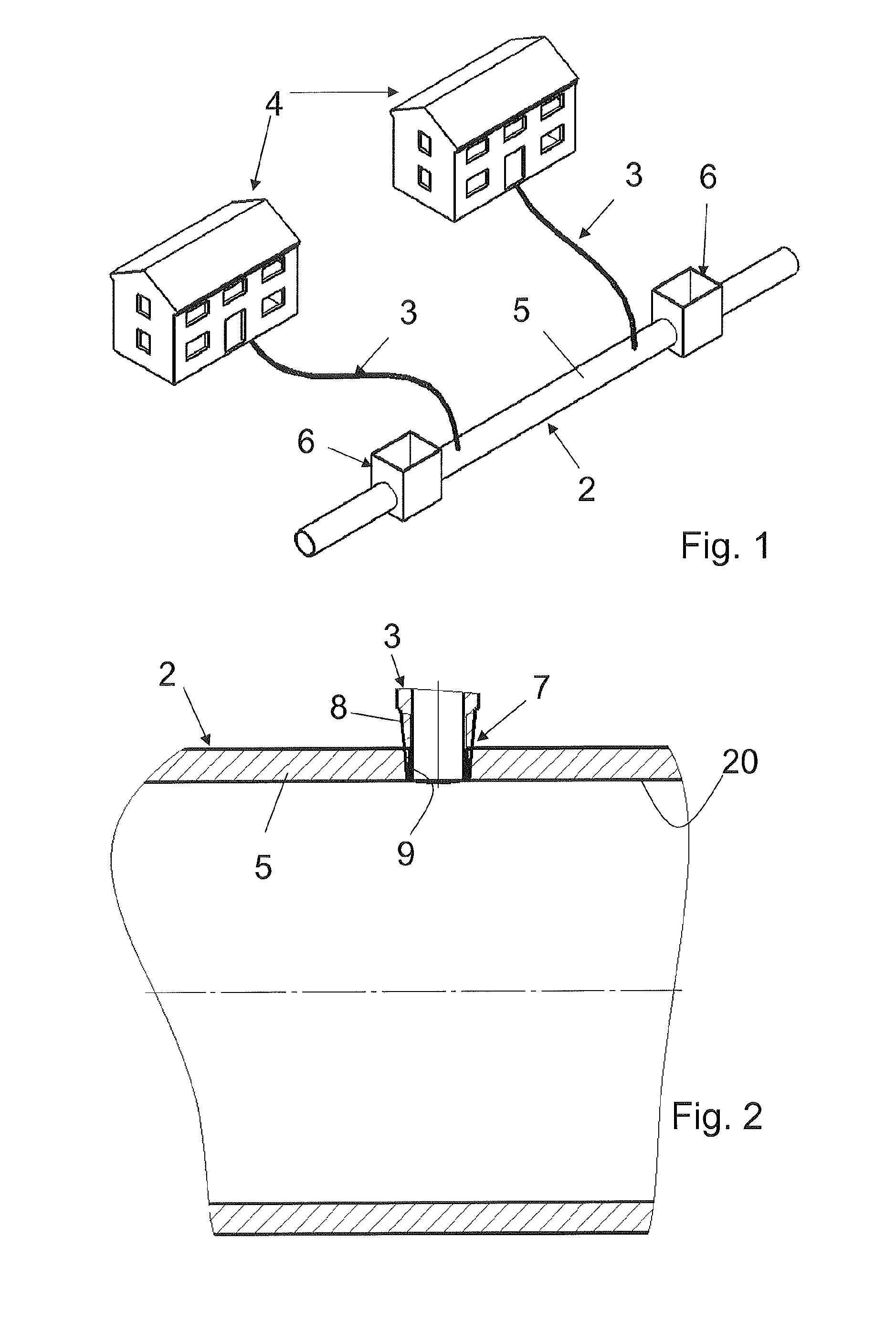
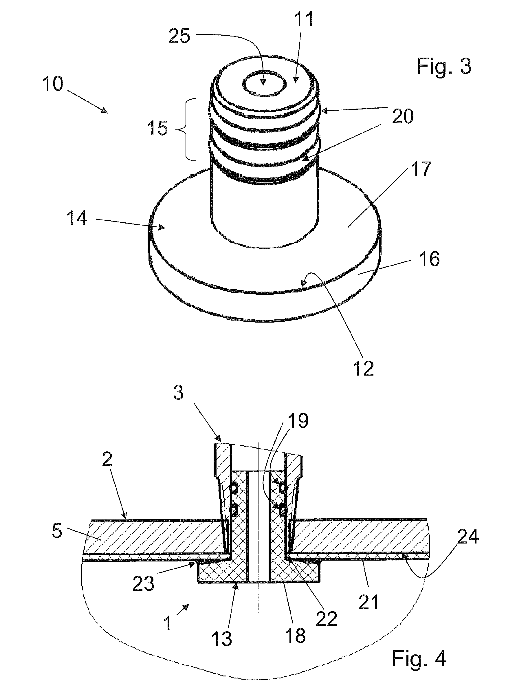
[0036]the pipe joining device 1 is shown in FIG. 3 and is adapted for use at the junction of a first pipe 2 with a ferrule (branch) pipe 3 in a mains water supply system. The pipe joining device 1 is adapted to form a junction between a rehabilitated first pipe that includes a layer of thermoplastic on its internal surface and the branch pipe. FIG. 1 shows a part of a common water supply system that extends underground. The ground has not been shown for clarity. The system comprises the main or first pipe 2 and includes the two branch pipes 3, which deliver the water from the first pipe 2 to the residences 4. The branch pipes 3 intersect the first pipe 2 and extend through the wall 5 of the first pipe 2 so as to be in communication with the water present therein. The water supply system also includes two inspection chambers 6. The water supply system is pressurised and therefore the pipe work and pipe joining device will need to be capable of withstanding pressures in the region of ...

second embodiment

[0046]FIG. 5 shows the pipe joining device 1. Like reference numerals have been used for like parts. In this embodiment, the two O-ring sealing elements 20 and grooves 19 have been replaced with a bead of silicone material 30 that is laid around the outside of the tubular portion 12. This material expands on contact with water to form a seal between the tubular portion 11 of the pipe joining device 1 and the branch pipe 3. Such contact with water occurs when the pipes 2, 3 are refilled once repairs are complete.

[0047]It will be appreciated that further modifications to the pipe joining device 1 could be made. In particular, the thermoplastic materials may be reinforced with fibres of various materials. The branch pipe 3 may be of thermoplastic material or may be lined. Indeed, where a new thermoplastic first pipe has been laid, this pipe joining device and method allows a quick and simple method of attaching branch pipe lines to the first pipe line. The sealing element 20 may be suc...


PUM

PropertyMeasurementUnit
Lengthaaaaaaaaaa
Thicknessaaaaaaaaaa
Sizeaaaaaaaaaa

Abstract

A pipe joining device for forming a junction in pressurised and rehabilitated pipes between a first pipe and a branch pipe, the pipe joining device including a substantially rigid body at least in part of thermoplastic, the body including a first pipe sealing portion adapted to form a seal with the first pipe and a branch pipe sealing portion adapted to form a seal with the branch pipe.

Description

CROSS-REFERENCE TO RELATED APPLICATIONS[0001]The present application is a continuation of pending International patent application PCT / GB2010 / 051631 filed on Sep. 30, 2010 which designates the United States and claims priority from United Kingdom Patent Application 0917158.8 filed on Sep. 30, 2009, the content of which is incorporated herein by reference.FIELD OF THE INVENTION[0002]The present invention relates to a pipe joining device for forming a junction in pressurised pipes between a first pipe and a branch pipe. In particular, it relates to a rehabilitated pipe junction forming device of thermoplastics for joining a branch pipe to the wall of a rehabilitated main pipe having a thermoplastic component in a pressurised water system. It also relates to a method of forming a junction between a branch pipe and a rehabilitated first pipe that is lined with a layer of thermoplastic using a pipe joining device in a system subject to pressure.BACKGROUND OF THE INVENTION[0003]The term ‘...

Claims


Application Information

Patent Timeline
IPC IPC(8): F16L41/08F16L1/00B32B37/14
CPCB29C65/06B29C65/20B29C65/4895B29C66/322B29C66/52241B29C66/55B29C66/52296B29C66/72321F16L41/10F16L47/02F16L47/28F16L55/179B29C65/3632B29C66/61Y10T137/0447B29C66/131B29C66/112
Inventor LINDSEY, KEVIN ALBERTTURNER, LAURENCE PAUL
Owner EPL COMPOSITE SOLUTIONS LTD
Why Eureka
Try Eureka