Check patentability & draft patents in minutes with Patsnap Eureka AI!

Apparatus for measuring a propagation velocity of a blood pressure wave

Inactive Publication Date: 2012-07-12
CNR DIPARTIMENTO DI MEDICINA +1
View PDF12 Cites 14 Cited by
  • Summary
  • Abstract
  • Description
  • Claims
  • Application Information

AI Technical Summary

Benefits of technology

[0024]It is a further particular feature of the present invention to provide an apparatus capable of measuring the propagation velocity of the pressure wave of the arterial system in a simple way, exceeding the difficulty of measuring the local pressure wave in the arterial vessels, such as carotid artery and femoral artery.
[0025]It is still a further feature of the present invention to provide an apparatus capable of monitoring precisely and in a substantially continuous way variation of the propagation velocity of the pressure wave of the arterial system during diagnostic examinations such as, for example, pharmacological stress test, physical stress test and stress test of desired other nature.
[0033]In particular, said first application point of the central arterial system of said first sensor of cutaneous vibrations is at the heart, in order to measure the vibration generated by the heartbeat, whereas said second application point of said second sensor of cutaneous vibrations is at an arterial vessel, in order to measure the vibration caused by the deformation of the vessel responsive to the movement of said pressure wave. In particular, both sensors of vibration are applied in a light contact with the skin of the patient without applying any pressure. This is particularly relevant especially at the arterial vessels since the adoption of cutaneous sensors makes it possible to eliminate measurement errors due to a pressure application to the vessels. This way, in fact, it is avoided that, at the application point of the sensor, there is a restriction of the cross section and of the shape of the arterial vessel.
[0034]Alternatively, said first and second local application points of said first and second sensors of cutaneous vibrations are at a same arterial vessel at a predetermined distance from each other, in order to measure a local cutaneous vibration by the deformation of the vessel in each of said points located on said same arterial vessel. This way, the sensors applied without any pressure to the same arterial vessel do not alter the hemodynamics of the blood flow and provide a careful and precise measurement of the pressure wave velocity.
[0041]This way, it is possible to apply the second sensor for a long time on the patient's skin, at the application point of the sensor near the arterial vessel, without any discomfort for the patient, and measuring continuously the second cutaneous vibration signal. The propagation velocity of said pressure wave, i.e. the PWV, is then calculated continuously, and a chart can be produced during diagnostic examinations such as, for example, a stress test.

Problems solved by technology

Even if largely used, this technique is affected by some limits owing to problems of estimating the distance between the measurement sites as well as difficulty of detecting the pressure wave in the femoral artery in obese subject and possible overestimation of the PTT in the presence of stenosis, i.e. a disease that involves narrowing of a duct, in this case a blood vessel.
A limit of this method is that the measurement of the pressure wave in an artery has some practical difficulty.
One of the problems of these systems is the difficulty of a continuous and long monitoring.
Therefore, none of these apparatus offers a solution that is operatively easy, and is adapted to a continuous monitoring lasting several minutes, as required in certain diagnostic examinations such as, for example, pharmacological stress test and physical stress test.
The drawback of this system is that the propagation of the cardiac tones along the tissues is attenuated very quickly with the distance, and consequently the remote site has to be very close to the heart, and in any case the sonic signal to analyze is very weak and mistakable with the background noise.
Firstly, the pressure sensor has to be kept still, since a minimum movement affects the detection.
These tools are however very uncomfortable for the patient same and not completely effective if the patient effects its normal activities.
In fact, the application of the sensor causes a shrinkage of the cross section of the arterial vessel perturbing the normal dynamic behavior of the blood and altering the measurement.
Furthermore, the pressure sensor is of difficult application since for keeping enough pressure on the vessel it is necessary the presence of an operator or the use of belts or collars of difficult application which tie the patient to stay still.
In particular, the pressure of the operator cannot be steady and causes transmitting to the pressure sensor a noise generated by a wrong application.
Furthermore, in certain zones of the body, such as on the neck, a belt is of difficult application.

Method used


Image

  • Apparatus for measuring a propagation velocity of a blood pressure wave
  • Apparatus for measuring a propagation velocity of a blood pressure wave
  • Apparatus for measuring a propagation velocity of a blood pressure wave

Examples


Embodiment Construction

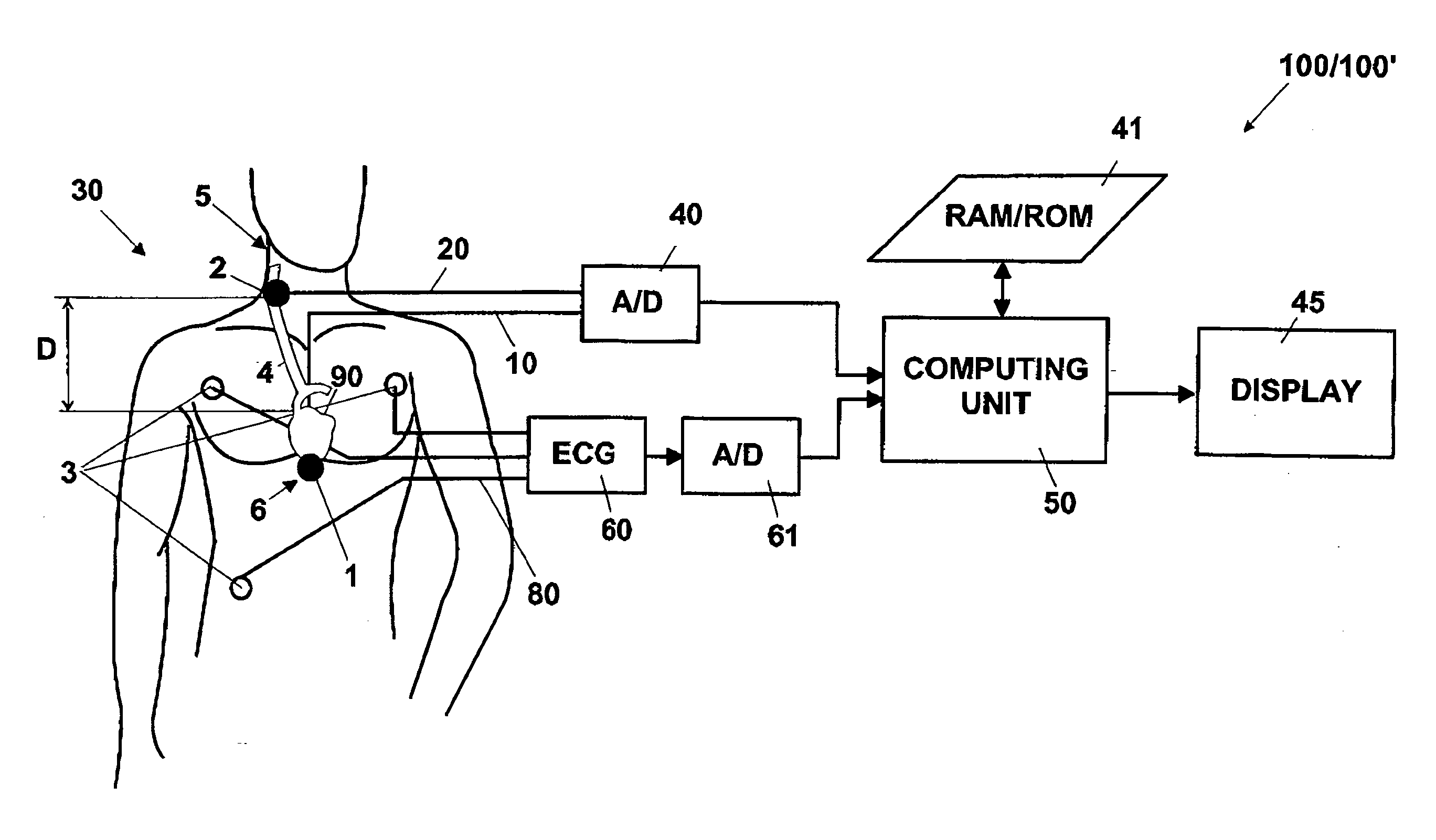
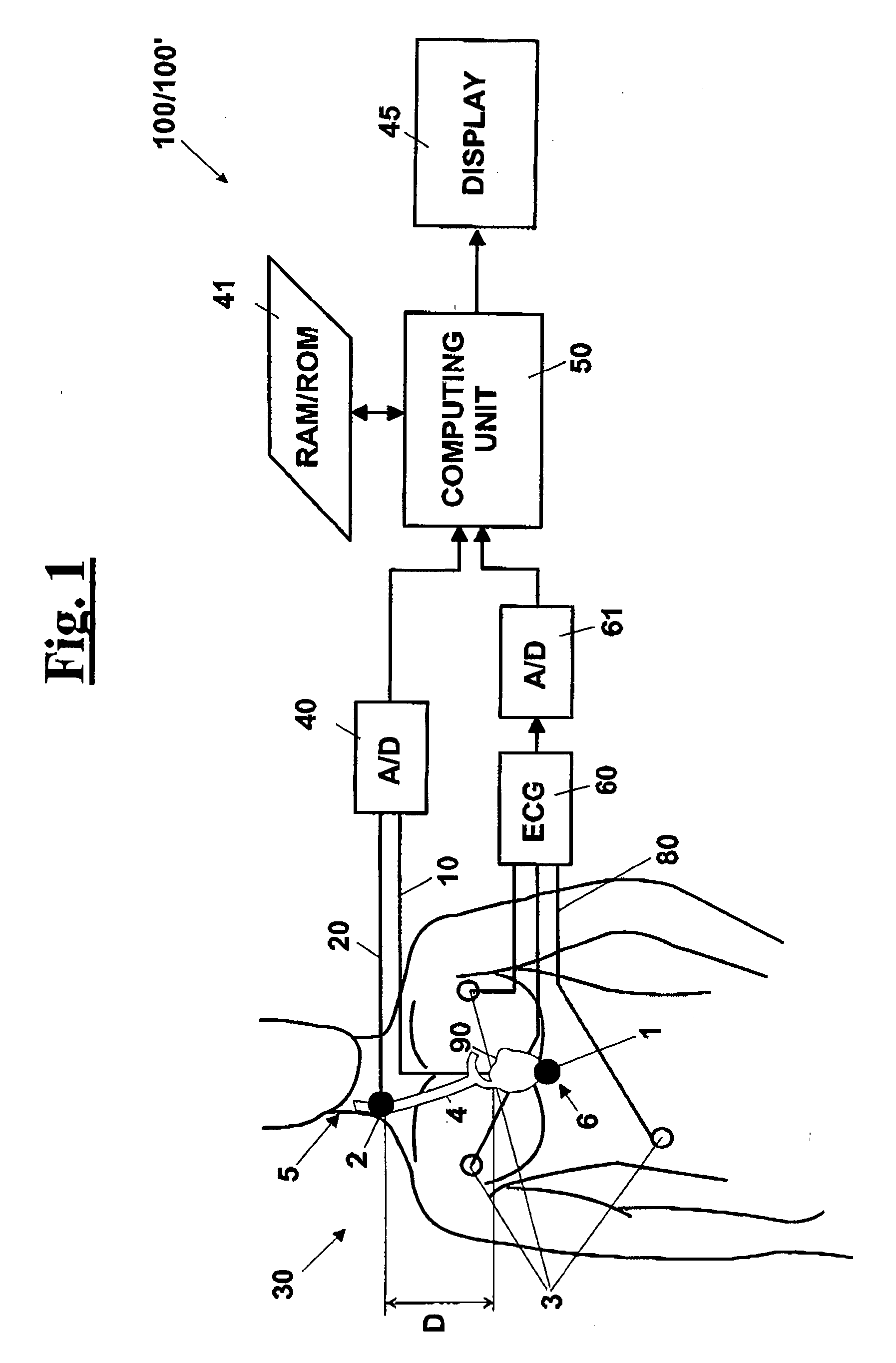
[0064]With reference to FIG. 1, a diagrammatical simplified view is shown of an apparatus 100 / 100′, according to the invention, for measuring the propagation velocity of a pressure wave. In particular, apparatus 100 comprises a first sensor of cutaneous vibrations 1 mounted in a first application point, in particular according to a first configuration, mounted at the heart, in order to measure a vibration generated by heartbeat 90, creating a corresponding first cutaneous vibration signal 10, and a second sensor 2, which is adapted to measure a local cutaneous vibration generated in a predetermined point of an arterial vessel 4, creating a corresponding second cutaneous vibration signal 20. More precisely, second sensor 2 detects the vibration caused by the deformation of vessel 4 responsive to the progression of the pressure wave. This way, it is possible to apply second sensor 2 for a long time on the patient's skin, at the application point of the sensor near arterial vessel 4, w...


PUM


Abstract

An apparatus for measuring the propagation velocity of a pressure wave comprises a first sensor of cutaneous vibration to measure a vibration generated in a first application point, creating a corresponding first signal, and a second sensor of cutaneous vibrations to measure a local cutaneous vibration generated in second point of an arterial vessel, creating a corresponding second signal caused by the deformation of the vessel responsive to the progression of the pressure wave in the vessel. A control unit detects on the first and second signal respectively a first instant time T1 and a second instant time T2 corresponding to a same event of a cardiac cycle. On the basis of T1 and T2 a transit time PTT (Pulse Transit Time) is calculated of the pressure wave and then the propagation velocity is measured of the pressure wave as the ratio between the length of the path arterial.

Description

FIELD OF THE INVENTION [0001]The present invention relates to an apparatus for measuring the propagation velocity of a pressure wave in the central arterial system, by detecting signals of the cutaneous vibrations generated by the heart and signals of the cutaneous vibrations generated by the movement of the blood in an artery.[0002]Furthermore, the above described apparatus is adapted to effect a measurement at different points of a same arterial vessel.[0003]Furthermore, the invention relates to an apparatus for measuring variation of the propagation velocity of a pressure wave in the central arterial system.DESCRIPTION OF THE PRIOR ART [0004]As well known, increasing the stiffness of blood vessels is a new and early index of increased cardiovascular risk. Different techniques exist for determining the arterial stiffness at systemic, regional and local levels. In particular, the regional arterial stiffness, i.e. the stiffness measurement in a determined portion of an artery, can b...

Claims


Application Information

Patent Timeline
IPC IPC(8): A61B5/021
CPCA61B5/021A61B5/0285A61B5/02133A61B5/02125
Inventor GEMIGNANI, VINCENZOFAITA, FRANCESCOBIANCHINI, ELISABETTA
Owner CNR DIPARTIMENTO DI MEDICINA
Features
  • R&D
  • Intellectual Property
  • Life Sciences
  • Materials
  • Tech Scout
  • Unparalleled Data Quality
  • Higher Quality Content
  • 60% Fewer Hallucinations
Learn More