Root resurfacing attachment for hand held gas powered edgers

a technology of root resurfacing and gasoline power, which is applied in the field of land-scaping, can solve the problems of affecting the efficiency of equipment grinding, and affecting the operation of equipment, so as to achieve the effect of efficient grinding of exposed roots

Active Publication Date: 2012-07-19
RBGONE
View PDF1 Cites 8 Cited by
  • Summary
  • Abstract
  • Description
  • Claims
  • Application Information

AI Technical Summary

Benefits of technology

[0011]To solve one or more of the problems set forth above, in an exemplary implementation of the invention, a root resurfacing attachment for a landscaping edger has a rotating threaded spindle, the root resurfacing attachment includes a rotating hub. The rotating hub includes an axial core with an inboard end and an opposite outboard end, an inboard flange with a first outer diameter at the inboard end, a plurality of evenly spaced ribs extending radially from the axial core, a central bushing channel with a noncircular cross section extending from the inboard flange into the axial core, and a central flange channel extending from the outboard end of the axial core to the central bushing channel. The ribs define a second outer diameter. A removable outboard flange assembly attaches to the outboard end of the rotating hub. The outboard flange assembly has a third outer diameter. An outboard flange attachment such as a threaded bolt or screw attaches the removable outboard flange assembly to the outboard end of the rotating hub. An inboard spindle bushing has a noncircular cross section sleeve configured to fit snugly in the central bushing channel, and a central threaded channel extending axially through the inboard spindle bushing and being threaded to threadedly engage the rotating threaded spindle of the landscaping edger. A plurality of parallel spaced-apart endless cutting chain loops are provided on the hub. Each cutting chain loop has an inner periphery and inner diameter, an outer periphery and outer diameter. Each cutting chain loop comprises an endless loop of connected chainsaw chain links, including a plurality of cutting links, drive links, and tie straps. Each cutting link includes a cutting surface at the outer periphery. Each drive link includes a rib engaging fin at the inner periphery. A plurality of spaced-apart spacer rings keep the adjacent cutting chain loops separated without interfering with cutting. Each spacer ring has an inner periphery and inner diameter, an outer periphery and outer diameter, and a width. Each spacer ring is disposed between adjacent cutting chain loops. The outer diameter of the spacer rings is less than the outer diameter of the cutting chain loops, so that the spacer rings do not interfere with cutting. The inner diameter of the spacer rings allows the spacer rings to slide onto the rotating hub. The first outer diameter is greater than the second outer diameter and the third outer diameter is greater than the second outer diameter.
[0016]A landscaping tool equipped with such a root resurfacing attachment may be used to efficiently grind exposed roots. The grinding occurs substantially evenly along the axial length of hub. A single chain loop may be replaced as needed. There chain loops have no free ends that may come loose. A shield protects a user from flying debris. The action of the chainsaw teeth of the cutting head, rotating clockwise at about 1000 to 4000 rpm, cuts, grinds down or resurfaces the protruding tree roots to the soil level very efficiently.

Problems solved by technology

When professionals such as landscapers; golf course maintenance crews; lawn maintenance and property managers, as well as individual homeowners attempt to cut the grass and maintain their lawns; they often encounter tree roots and even cypress knees that protrude above of soil level.
If a homeowner or professional attempts to use lawn mowing equipment over the exposed root, the chances are great that the spinning blade of the equipment will end up striking the protruding root and sustain substantial damage to one or more of the mower blade, spindle shaft, deck housing or even the motor.
Tree root strike damage could render the equipment totally inoperable.
The cost of repairs and or replacement could be substantial.
However, most homeowners and small commercial landscapers lack an appropriate tool for conveniently resurfacing a root.
Many who encounter roots are tempted to inappropriately use the tip of a chain saw for resurfacing.
However, this is highly inappropriate chain saw use and risks kickback damage to the saw and injury to the user.
Unfortunately, these devices are not well suited for grinding down (i.e., resurfacing) protruding tree roots.
When such devices are used to resurface a root, surrounding soil severely dulls and eventually destroys the cutting edges of the blade.
However, because of the different speeds, such a device has a strong tendency to travel in a circular path, making stabilization extremely difficult.
Another problem is inevitable loosening of the chain.
The pin and screw in Albertson are prone to failure, as they are subjected to considerable impacts and stresses during operation.
If either end becomes free, the device is extremely dangerous and self-destructive.
If both ends become free, the chain becomes a dangerous projectile.
Another problem is that the Albertson device does not allow adjacent rows of saw teeth to be positioned in a preferred arrangement.
Thus two right angled teeth may be adjacent to one another resulting in an uneven cutting path.
Moreover, the saw teeth are traveling at a less than optimal angled path, rather than a straight path.
Yet another problem with the Albertson device is that one damaged tooth may require replacement of the entire length of chain.
Frequently one tooth is damaged upon encountering a small stone.

Method used


Image

  • Root resurfacing attachment for hand held gas powered edgers
  • Root resurfacing attachment for hand held gas powered edgers
  • Root resurfacing attachment for hand held gas powered edgers

Examples


Embodiment Construction

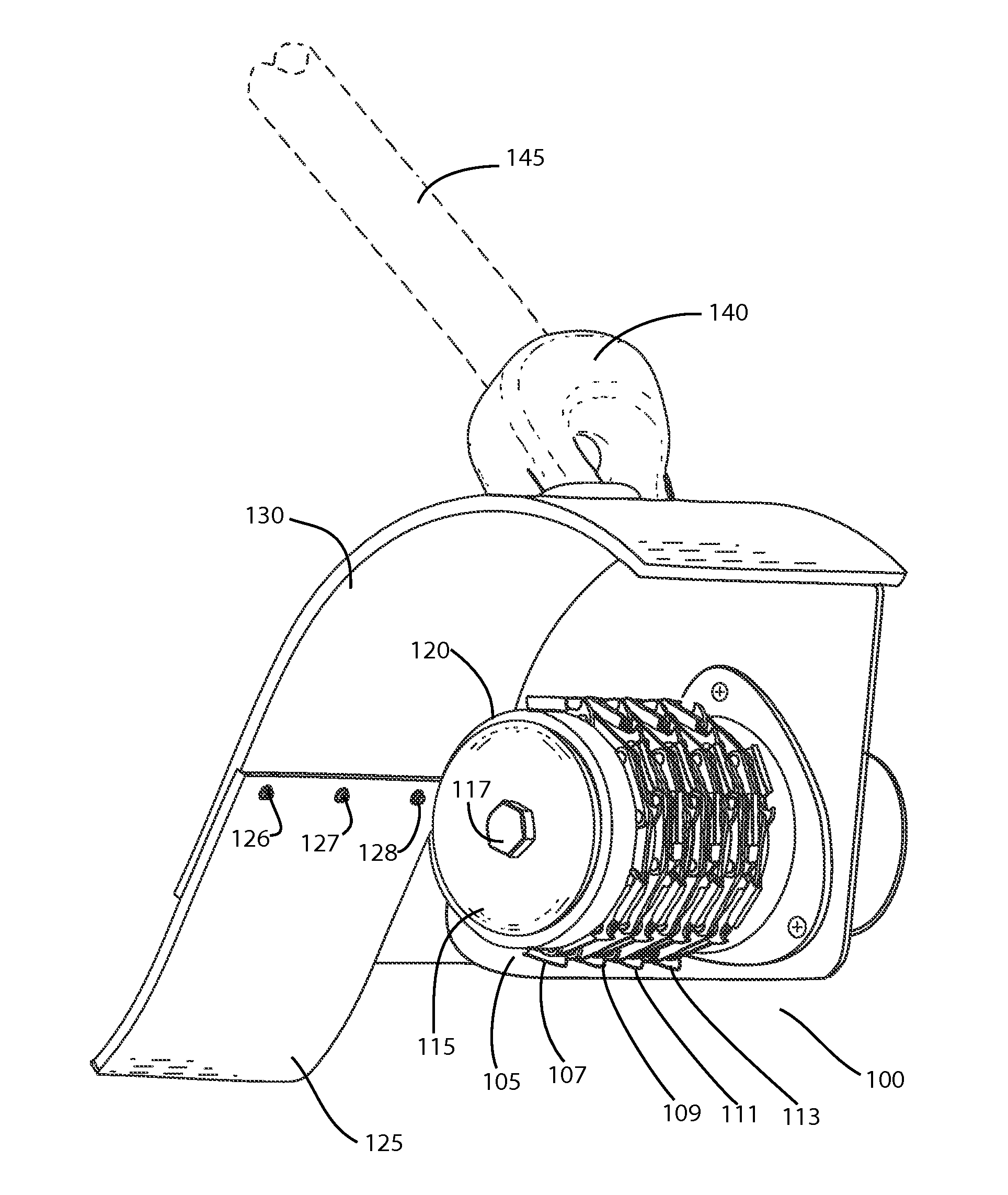
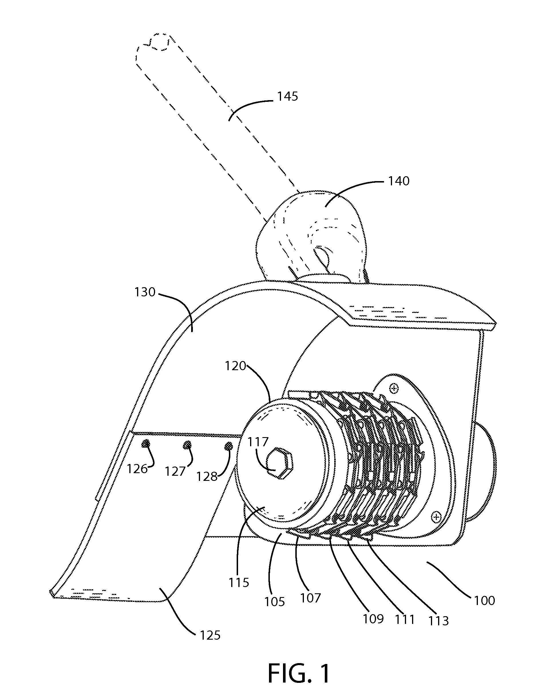
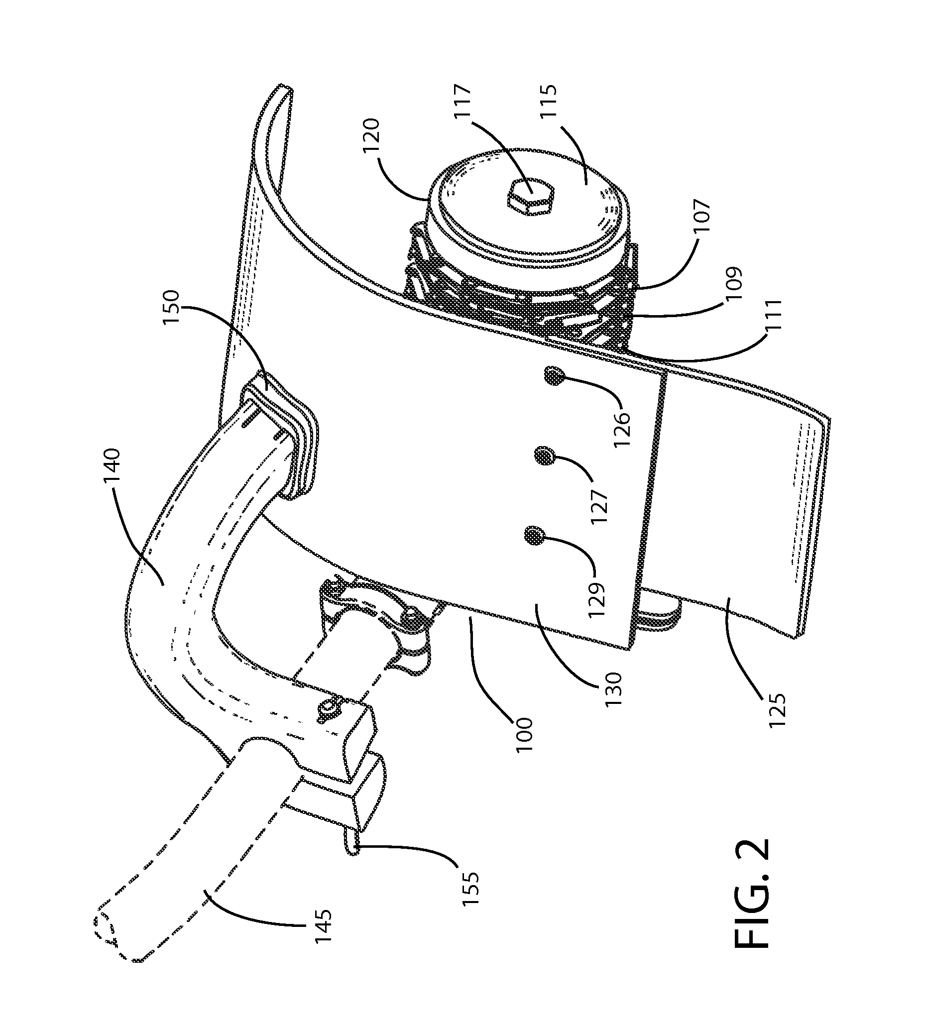
[0043]Referring to FIG. 1, a perspective view of an exemplary assembled root resurfacing attachment according to principles of the invention is provided. Shaft 145 comprises a part of a gasoline powered landscaping edger, such as, for example, the exemplary edger shown in FIG. 22. An engine 710 causes a cable or drive shaft that extends through the shaft 145 to rotate. Rotation of the cable or drive shaft powers a gear box or transmission 101, which causes a spindle 102 (FIG. 3) to rotate. Rotation of the spindle 102 typically drives a rotating blade used to edge a lawn. However, in accordance with the invention, the blade is removed from the spindle 102. A root resurfacing attachment according to principles of the invention is attached to the spindle 102, as discussed below.

[0044]A root resurfacing attachment 100 according to principles of the invention comprises a plurality of parallel spaced apart chainsaw chains 107-113 (hereinafter “cutting chains” or “chains”) mounted on a uni...


PUM

PropertyMeasurementUnit
outer diameteraaaaaaaaaa
inner diameteraaaaaaaaaa
widthaaaaaaaaaa

Abstract

A rotating cutting head includes multiple, separate, spaced-apart, parallel loops of chainsaw chains positioned around a central hub. The hub is attached to a spindle of a lawn edger. A safety shield is provided adjacent to the rotating cutting head. As the cutting head rotates, the chainsaw chains cut the tree roots. The rotating cutting head is used for resurfacing exposed tree roots to avoid tripping hazards and tree root strike damage to residential and commercial lawn maintenance equipment.

Description

RELATED APPLICATION[0001]This application is a continuation in part and claims the benefit of priority of U.S. Nonprovisional application Ser. No. 13 / 068,568 filed on May 16, 2011, which is a nonprovisional and claims the benefit of priority of U.S. Provisional Patent Application No. 61 / 396,594 filed on Jun. 1, 2010, the entire contents of which are incorporated herein by this reference and made a part hereof.FIELD OF THE INVENTION[0002]This invention relates generally to landscaping, and, more particularly, to root resurfacing attachment for gasoline powered edgers.BACKGROUND[0003]When professionals such as landscapers; golf course maintenance crews; lawn maintenance and property managers, as well as individual homeowners attempt to cut the grass and maintain their lawns; they often encounter tree roots and even cypress knees that protrude above of soil level. If a homeowner or professional attempts to use lawn mowing equipment over the exposed root, the chances are great that the ...

Claims


Application Information

Patent Timeline
Patent Type & Authority Applications(United States)
IPC IPC(8): A01G3/08A01G23/00
CPCA01G23/067Y10T83/909
Inventor VOYER, JEFF C.PEACOCK, WILLIAM D.
Owner RBGONE
Why Eureka
Try Eureka