Coal flow balancing devices

a technology of flow balancing and coal, which is applied in the direction of bulk conveyors, combustion process, lighting and heating apparatus, etc., can solve the problems of inefficient combustion, non-uniform coal particle distribution, and various technical problems of operation and maintenance of coal systems, so as to reduce the non-uniformity of coal particle concentration and increase the uniformity of coal particle distribution

Inactive Publication Date: 2012-07-26
BABCOCK POWER SERVICES
View PDF18 Cites 30 Cited by
  • Summary
  • Abstract
  • Description
  • Claims
  • Application Information

AI Technical Summary

Benefits of technology

[0009]The subject invention is directed to a new and useful flow splitter for distributing solid particles flowing in a fluid through a piping system. The flow splitter includes a divider housing having an inlet configured to connect to an upstream pipe and having an outlet configured to connect to a plurality of downstream pipes, e.g., by way of a divider head. A divider body is mounted within the divider housing. A plurality of divider vanes is included, each extending from the divider body to the divider housing. The divider housing, divider body, and divider vanes are configured and adapted to reduce non-uniformity in particle concentration from the inlet and to supply a substantially equal particle flow from the outlet to each of the downstream pipes.
[0013]The invention also provides a coal piping system for delivering coal fines flowing in an air flow for combustion in a boiler. The system includes an upstream coal pipe for delivering coal fines from an upstream source, a divider housing having a circular inlet mounted to the upstream coal pipe and having a rectangular outlet mounted to a divider head leading to a pair of rectangular downstream coal pipes. A divider body is mounted within the divider housing. A plurality of divider vanes are included, each extending from the divider body to the divider housing. The divider housing, divider body, and divider vanes are configured and adapted to reduce non-uniformity in coal particle concentration from the inlet and to supply a substantially equal coal particle flow from the outlet to each of the downstream pipes. A pair of side kickers are included. Each side kicker is mounted in a respective one of the downstream pipes. Each side kicker protrudes inward with respect to an upstream portion of the respective downstream pipe for increasing uniformity in coal particle distribution downstream of the kicker. It is contemplated that the side kickers are mounted on opposed lateral sides of the respective downstream pipes. A pair of bottom kickers can also be included, each mounted in a respective one of the downstream pipes. The bottom kickers are both mounted on a similar side of each respective downstream pipe, e.g., both bottom kickers are mounted on the bottom side of their respective downstream pipe.

Problems solved by technology

As the coal particles travel in the air flow through the piping system, bends in the piping and the pipe geometry in general tend to cause non-uniform coal particle distribution.
Coal roping causes various technical problems for operation and maintenance of coal systems.
The poor distribution of coal particles can extend into the combustion zone, where localized imbalances in the fuel / air mixture tend to cause inefficient combustion and elevated emissions of NOx, CO, and other pollutants.
It can also cause elevated levels of unburned carbon in the fly ash, which will lower combustion efficiency.
Also, the highly abrasive nature of the coal rope impacting and scrubbing components of the coal piping and burning system causes extensive erosion of pipes and other components in the system, leading to frequent need for inspection, repairs, and replacement of parts.
If inspections, repairs and replacements are not performed in a timely manner, there is an elevated chance that abrasion from coal roping will cause expensive or dangerous failures of key components.
One component that is particularly problematic for coal roping is the dividing head at the junction between a single pipe upstream of two or more branching pipes downstream, as is commonly seen upstream of directional flame burner coal nozzles, for example.

Method used


Image

  • Coal flow balancing devices
  • Coal flow balancing devices
  • Coal flow balancing devices

Examples


Embodiment Construction

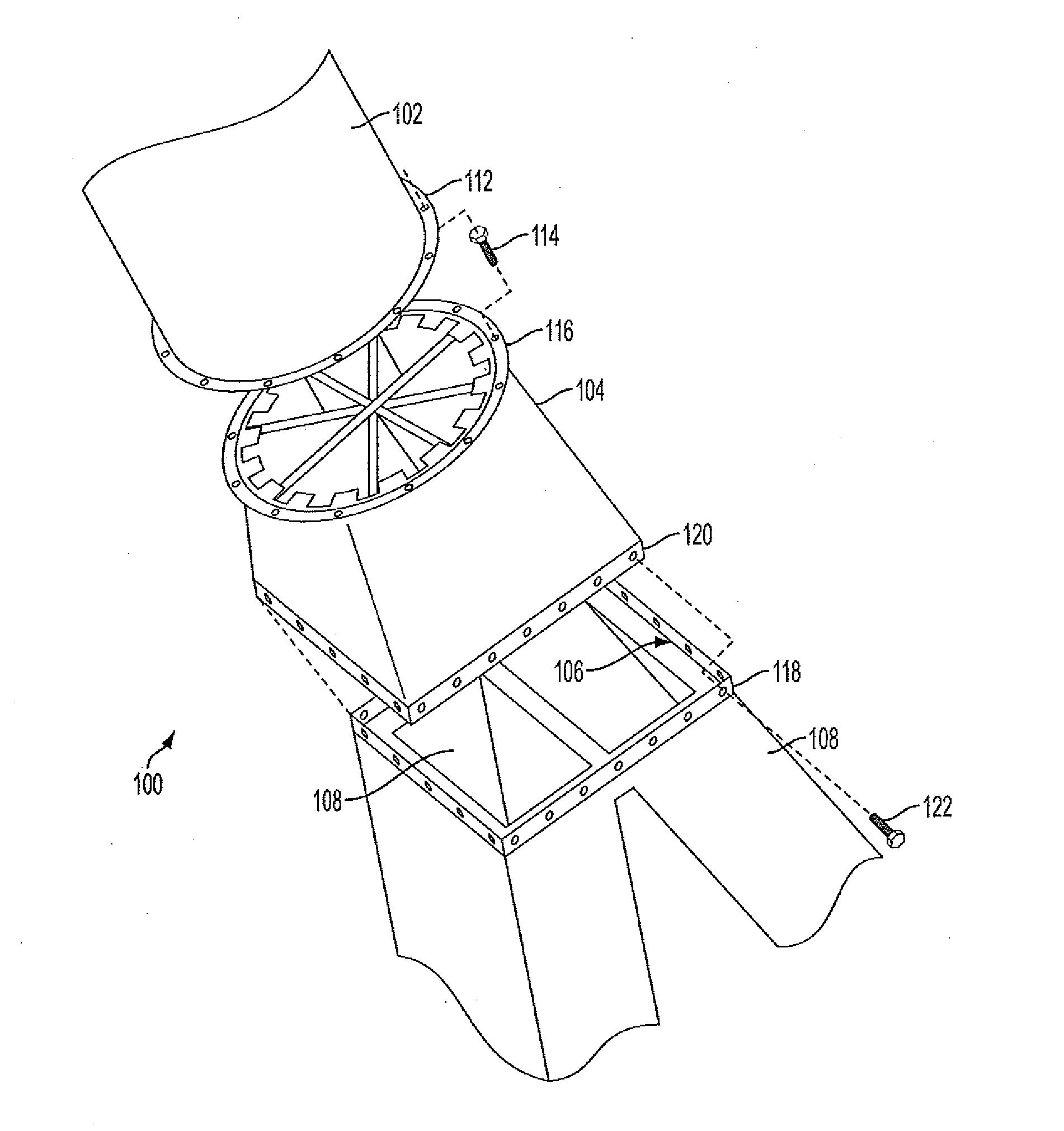
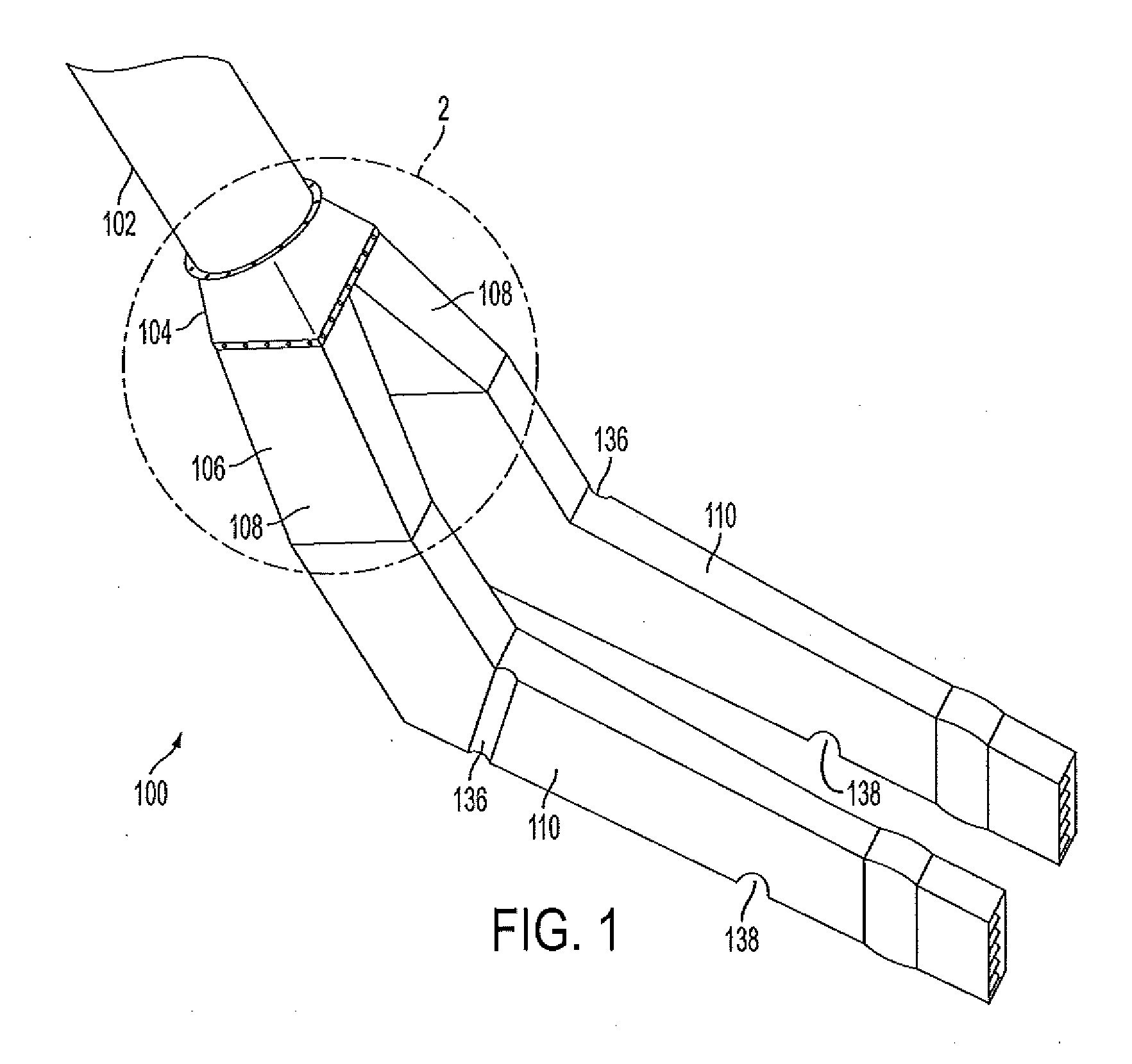
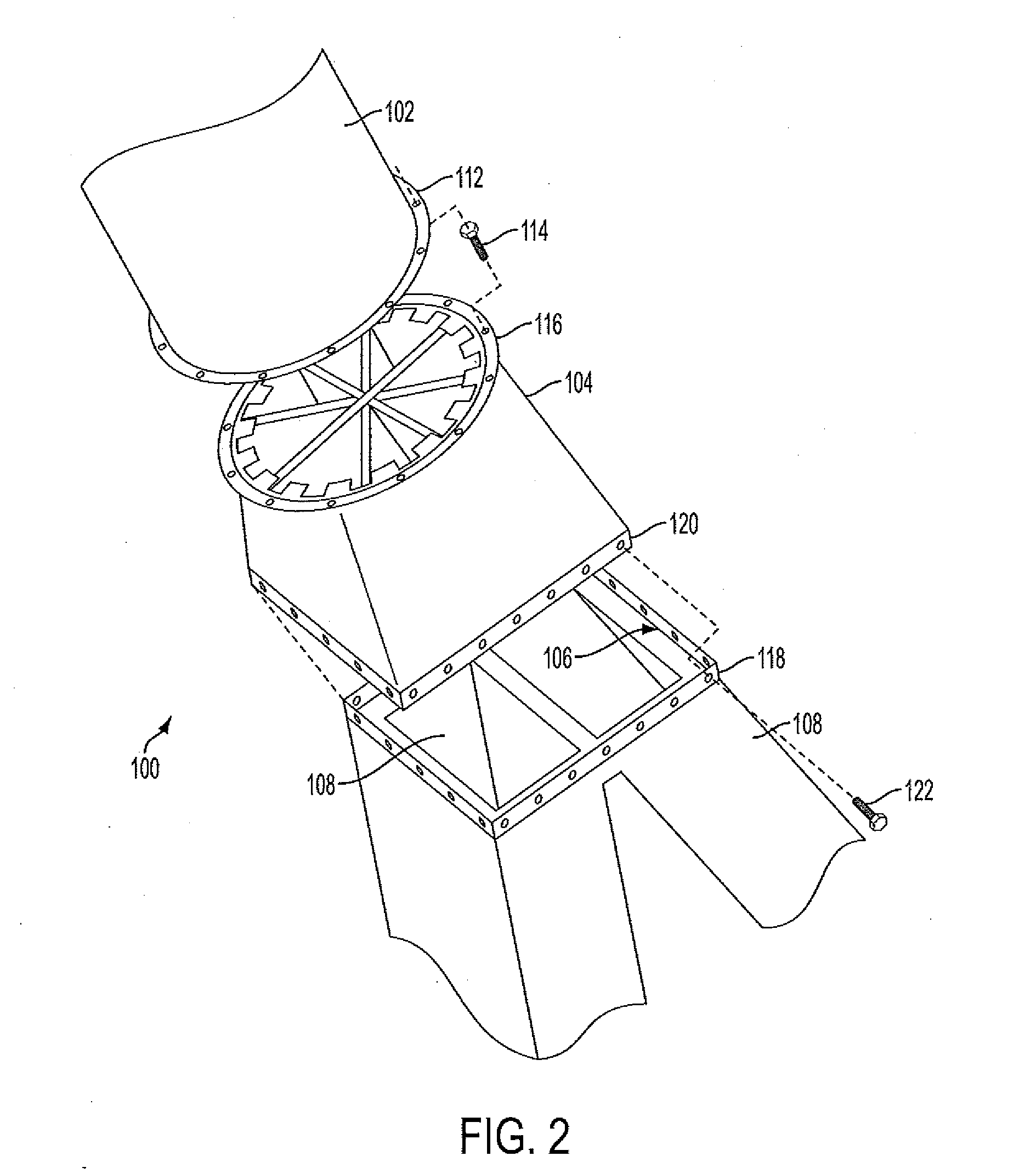
[0020]Reference will now be made to the drawings wherein like reference numerals identify similar structural features or aspects of the subject invention. For purposes of explanation and illustration, and not limitation, a partial view of an exemplary embodiment of a coal piping system in accordance with the invention is shown in FIG. 1 and is designated generally by reference character 100. Other embodiments of coal piping systems in accordance with the invention, or aspects thereof, are provided in FIGS. 2-4, as will be described. The systems and methods of the invention can be used to improve particle distribution downstream of dividing heads, for example in coal piping systems and the like.

[0021]Coal piping system 100 includes an upstream pipe 102 for conveying coal fines from an upstream source such as a pulverizer, in a flow of air to be burned in a downstream furnace or boiler. Flow splitter 104 connects to pipe 102 and includes internal components, which are described in det...


PUM


Abstract

A flow splitter distributes solid particles flowing in a fluid, such as coal particles flowing in air, through a piping system. The flow splitter includes a divider housing having an inlet configured to connect to an upstream pipe and having an outlet configured to connect to a plurality of downstream pipes, e.g., by way of a divider head. A divider body is mounted within the divider housing. A plurality of divider vanes is included, each extending from the divider body to the divider housing. The divider housing, divider body, and divider vanes are configured and adapted to reduce non-uniformity in particle concentration from the inlet and to supply a substantially equal particle flow from the outlet to each of the downstream pipes.

Description

BACKGROUND OF THE INVENTION[0001]1. Field of the Invention[0002]The present invention relates to distribution of solid particles flowing in a fluid, and more particularly to coal particle distribution in airflow through coal piping systems.[0003]2. Description of Related Art[0004]A variety of devices and methods are known in the art for delivering pulverized coal to coal fired burners. Of such devices, many are directed to improving particle distribution within coal piping systems for delivering coal to be combusted.[0005]Coal powered plants require an efficient means of supplying coal as fuel to produce heat power. Raw coal is typically pulverized in a coal pulverizer or mill to produce small coal particles or coal dust. The pulverized coal must then be delivered to a furnace or burner where it can be used for combustion. This is typically done with a coal piping system that utilizes air flows to transport pulverized coal particles from the mill or pulverizer to a nozzle where coal...

Claims


Application Information

Patent Timeline
Patent Type & Authority Applications(United States)
IPC IPC(8): F23K3/22
CPCB65G53/528F23K2203/105F23K3/02
Inventor ZARNESCU, VLADCOURTEMANCHE, BONNIEZHANG, JILIN
Owner BABCOCK POWER SERVICES
Why Eureka
Try Eureka