Process for the adjustment of a laser light spot for the laser processing of work pieces and a laser device for the performance of the process

a laser light spot and work piece technology, applied in the direction of manufacturing tools, laser beam welding equipment, welding/soldering/cutting articles, etc., can solve the problems of negative effect on production costs and undesirable effects

Active Publication Date: 2012-07-26
LEISTER TECHNOLOGIES
View PDF3 Cites 4 Cited by
  • Summary
  • Abstract
  • Description
  • Claims
  • Application Information

AI Technical Summary

Benefits of technology

[0017]Generally, the proposed process according to the invention can be used in conjunction with a fiber laser or a diode laser. Fiber lasers are a special form of the solid state laser and have a significantly better beam quality than diode lasers. The laser beam exiting from the laser aperture is distinguished by an extremely small divergence. The energy density distribution of the beam profile, i.e. the Gauss profile of the energy density, is multiple times narrower than that of a diode laser of the same power. This makes a fiber laser especially well suited for the laser processing of work pieces.

Problems solved by technology

If the width of the welding seam or the welding contour is wider than the diameter of the laser light spot that is determined by the optical system, this will always require additional process time which has an negative effect on production costs and is therefore undesirable.

Method used


Image

  • Process for the adjustment of a laser light spot for the laser processing of work pieces and a laser device for the performance of the process
  • Process for the adjustment of a laser light spot for the laser processing of work pieces and a laser device for the performance of the process
  • Process for the adjustment of a laser light spot for the laser processing of work pieces and a laser device for the performance of the process

Examples


Embodiment Construction

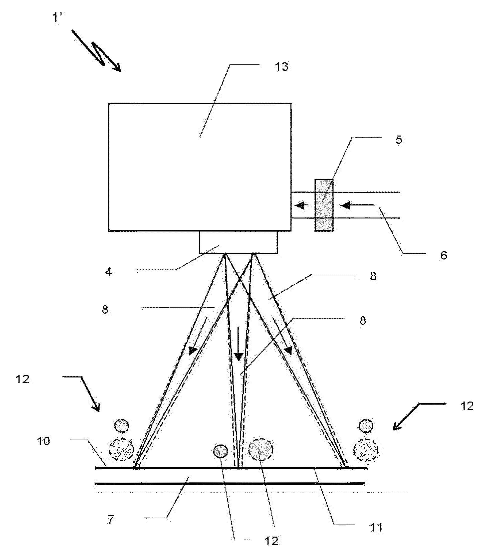
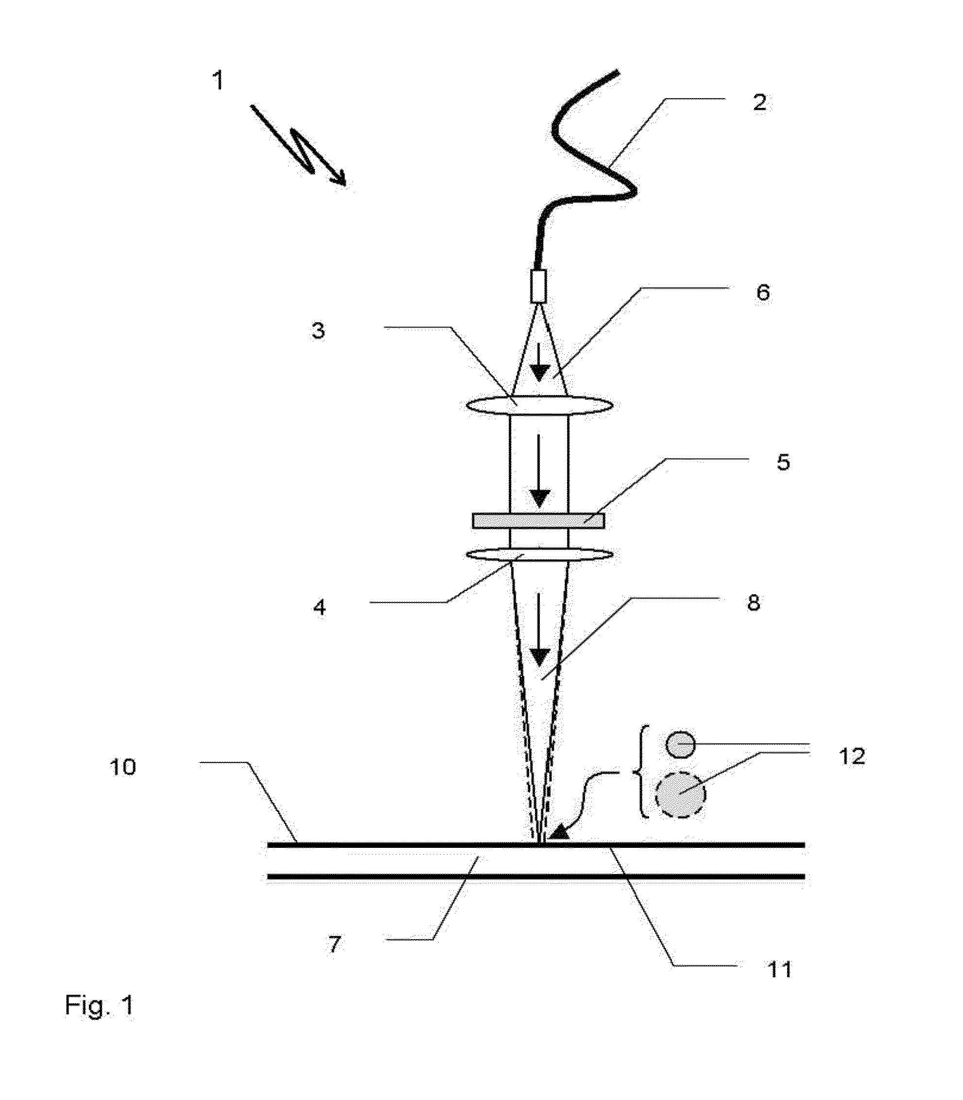
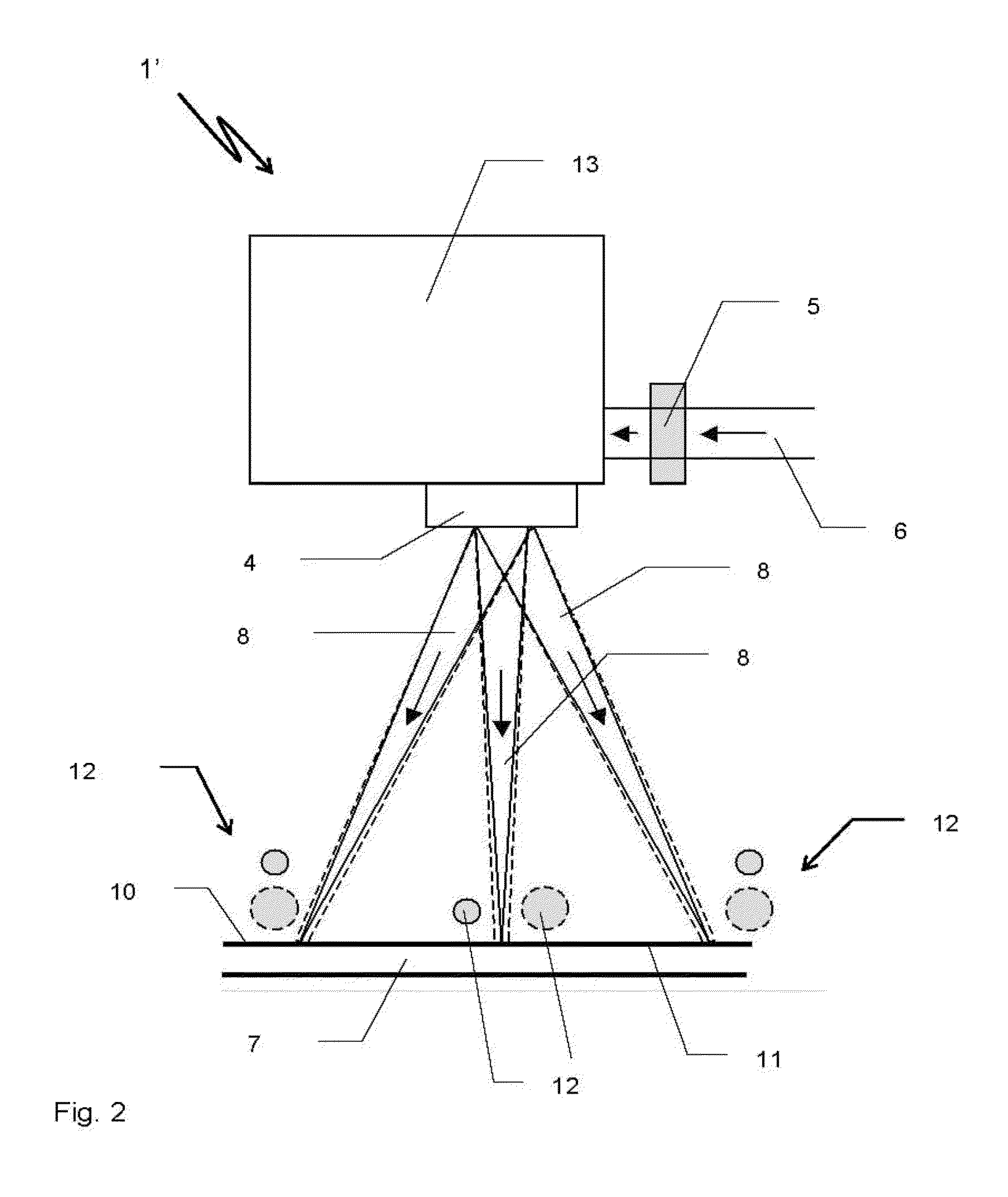
[0030]A laser device 1 shown in principle in FIG. 1 comprises a laser (not shown), an optical fiber 2 following the laser, a collimating lens 3, and a focusing lens 4, as well as a diffractive optical element 5 (DOE) that is arranged between the collimating lens 3 and the focusing lens 4. From the optical fiber 2, an original laser beam 6 exits that is collimated by the collimating lens 3, is shaped by the following DOE 5, and, focused by the focusing lens 4, is directed at a work piece 7 as a resulting laser beam 8. The laser beam 8 is composed of partial laser beams 9 (not shown), with the focal plane 10 of the laser device 1 coinciding with the surface 11 of the work piece 7. On the surface 11 of the work piece 7, the resulting laser beam 8 generates a laser light spot 12 of high intensity for the laser processing of the work piece 7. The diameter of the laser light spot 12 depends on the design of the DOE 5. By means of different DOEs 5, it is possible to generate laser light sp...


PUM

PropertyMeasurementUnit
diameteraaaaaaaaaa
thermal conductivityaaaaaaaaaa
poweraaaaaaaaaa

Abstract

The invention relates to a process for the adjustment of a laser light spot of high intensity for the laser processing of work pieces as well as a laser device for performing the proposed process. The laser device comprises a laser emitting a laser beam and at least one focusing lens for converging the laser beam as well as an optical operating element for adjusting the beam diameter of the laser beam. The invention proposes to use as operating element a diffractive optical element that separates the laser beam emitted by the laser into partial laser beams, with the partial laser beams generated by the diffractive optical element being assembled to form a resulting laser beam that acts on the work piece. By means of a suitable design of the diffractive optical element it is possible to adjust, in particular enlarge, the diameter of the laser light spot as required.

Description

CROSS-REFERENCE TO RELATED APPLICATION[0001]The present application claims priority under 35 USC §119 to European Patent Application No. 11 000 485.0 filed Jan. 21, 2011, the entire disclosure of which is incorporated herein by reference.TECHNICAL FIELD OF THE INVENTION[0002]The invention relates to a process for the adjustment of a high intensity laser light spot for the laser processing of work pieces, preferably for laser plastic welding of work pieces to be joined, by means of a laser device, as well as a laser device for performing the process. The laser device comprises a laser emitting a laser beam and at least one focusing lens for converging the laser beam as well as an optical operating element for adjusting the beam diameter of the laser beam, with the optical operating element configured as a diffractive optical element that separates the original laser beam into a bundle of partial laser beams that are directed at the work pieces.DESCRIPTION OF THE RELATED ART[0003]When...

Claims


Application Information

Patent Timeline
Patent Type & Authority Applications(United States)
IPC IPC(8): B23K26/06
CPCB23K26/0608B23K26/0652B23K26/0676B29C65/1674B23K26/3246B29C65/16B29C65/1664B23K26/0734B23K26/324B23K2103/30
Inventor GUBLER, ULRICHVOGLER, DANIELRAAB, CHRISTOPH
Owner LEISTER TECHNOLOGIES
Why Eureka
Try Eureka