Hydrokinetic energy transfer device and method

a technology of hydrokinetic energy and transfer device, which is applied in the direction of electric generator control, vessel construction, marine propulsion, etc., can solve the problems of inefficiency of design that has been tried, not scale well to a larger design, and suffer from one or more major flaws in the various configurations of hydrokinetic energy capture device in the prior art, so as to improve efficiency and reduce the cost. , the effect of reducing the number of problems

Inactive Publication Date: 2012-07-26
SCALE TERA RENEWABLE ENERGY L L C
View PDF1 Cites 35 Cited by
  • Summary
  • Abstract
  • Description
  • Claims
  • Application Information

AI Technical Summary

Benefits of technology

[0011]The present invention combines a novel, efficiency enhancing, light weight and low cost central structure and buoyancy system with a novel low cost, and highly reliable drive train in an innovative system design to create a large, but relatively light-weight hydrokinetic turbine that achieves disruptively low deployment cost and low Cost of Electricity (COE), in high volumetric flow rate, low velocity (1-3 m / s) marine currents. This same innovation is directly applicable to wind turbines, most especially, off-shore wind turbines, where efficiency, weight, reliability, cost (capital, deployment and O&M) and scalability are keys to competitive COE. Such a system dramatically opens up the scope of large, low velocity currents world-wide that are viable for use in cost competitive hydrokinetic electricity generation in ocean and tidal currents and potentially rivers.
[0012]The present invention solves the problem of the use of large mass, direct drive permanent magnet drive trains by achieving high reliability via its alternative drive train approach. This innovation utilizes a relatively large hollow tube as the main structural component of the turbine. The rotor system is mounted to and rotates around this tube, utilizing low friction, high reliability and very high torque bearing surfaces such as are used in ship propeller shafts and very large conventional hydro dam turbines. The innovative drive train utilizes a gear that is directly attached to the large diameter rotor structure and is therefore inherently of a very large diameter in this overall turbine design. This large but relatively light weight gear, when mated with a much smaller gear on a gearbox (or directly to a generator in some cases), provides a significant speed ratio increase on the front end, prior to the gearbox (nominally 20:1), in a highly reliable and low cost and light weight mechanism. This speed up allows the use of a very simple (nominally 10:1, single stage), low cost and highly reliable gearbox on the front end of the generator and the use of low cost, moderately high speed (500-2000 rpm) and relatively light weight generator. The gearing system between the large tube and the shaft on the gearbox can be a silent chain, meshing gear, tire based gearing or other mechanism. For example, when compared to a generator / drive train system in a conventional direct drive hydrokinetic (or wind) turbine, this innovation will be on the order of 20-30% the cost, similar reliability, and 20-30% of the volume and weight. For example, a direct drive 4.25 megawatt wind turbine generator from The Switch, Vantaa, Finland, weighs approximately 85 tons; while in the present invention, that same capability would weigh approximately 15-20 tons. The 60-70 ton weight savings gets multiplied many times at the platform level for off-shore floating wind, when the benefits to the rest of the structure, from having less weight at the top of the tower are factored in. The benefits of this in terms of the COE at the system level is highly disruptive, potentially bringing it down to 25-50% of the COE of competitive systems targeted at slow (1-3 m / s) marine currents, as well as off-shore wind turbines.

Problems solved by technology

All the various configurations of hydrokinetic energy capture devices in the prior art suffer from one or more major flaws.
First of all, efficient systems have been of very small design that do not scale well to a larger design.
Those larger designs that have been tried are inefficient with a very high cost per kilowatt hour and inefficient use of the flow resource.
All systems have suffered from difficult installation challenges.
Moreover, most of the prior art systems need a relatively fast current (approximately 3+ m / s) to be semi-viable, even with government subsidies.
Accordingly, given the cost of the prior art devices, their inefficiency and the cost of installing the devices, the energy they can extract from the fluid motion and later used for purposes such as electricity generation is not cost competitive with other methods of extracting energy and utilizing it for purposes such as electricity generation, water desalinization and hydrogen or other chemical production.
At this point, no renewable power source, which can scale to industrial power levels (wind, solar, geothermal, etc.), has shown that it can match the COE of current methods of generating electricity by extracting energy from fossil fuels.
One key problem in designing a viable large hydrokinetic turbine is the size, mass, cross sectional area and complexity of the drive train and supporting structure.
This much larger generator utilizes significantly more material, including rare earth magnetic materials, which are in short supply and pose a national security problem, as most of it is mined in China, who is rationing the supply to global markets and keeping much of its production for internal uses.
Although the high ratio gearbox has been shown to be a key reliability issue for these systems, for cost, weight and size requirements, this drive train is still the predominant one used in hydrokinetic devices, as well as modern wind turbines.
The benefits of this in terms of the COE at the system level is highly disruptive, potentially bringing it down to 25-50% of the COE of competitive systems targeted at slow (1-3 m / s) marine currents, as well as off-shore wind turbines.

Method used


Image

  • Hydrokinetic energy transfer device and method
  • Hydrokinetic energy transfer device and method
  • Hydrokinetic energy transfer device and method

Examples


Embodiment Construction

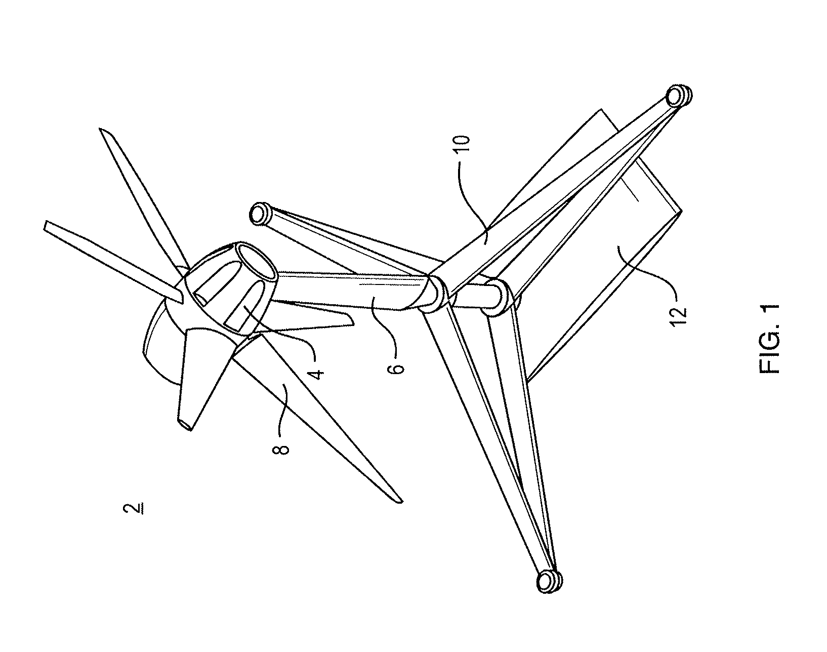
[0036]FIG. 1 shows one embodiment of the hydrokinetic device 2 of the present invention which includes a turbine body 4, to which is attached a turbine tower (or mast) 6. Also attached to the turbine body 4 is a set of blades 8, which are up stream of the tower 6 in this embodiment, but can also be downstream. In addition, this embodiment shows a tripod structure 10 and rotating buoyancy chamber 12, wherein the tower 6 rotates within the tripod 10 and rigidly connects the turbine body 4 to the chamber 12, which innovation may be utilized to offset the thrust imparted on the structure by the turbine body 4 via the tower 6. By utilizing the rotating chamber 12 to apply counteracting force, directly opposite of the force from the flow of fluid on the turbine components, less buoyancy overall must be provided and hence lower overall structural material use and cost results, especially in implementations such as supporting offshore floating wind turbines.

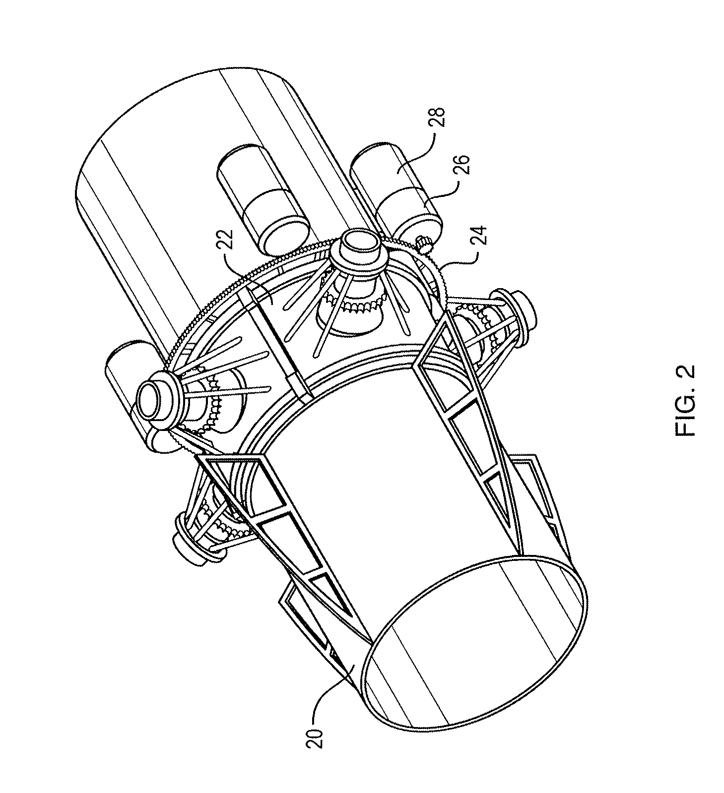
[0037]A cut away view of the turb...


PUM


Abstract

A device configured for the production of hydrokinetic energy that allows the efficient capture of energy from fluid in motion, especially slow flowing fluids. The device features an innovative structural design and drive train system as well as redundancy, which allows the device to be deployed in position, placed in service and maintained over its lifetime through the use of remotely operated vehicles. The device features one or more turbines, each turbine having an open center tube. The device features a buoyancy system including a plurality of thin walled modular buoyancy chambers with a redundant (re)pressurization system and remotely operated vehicle replaceable bladder modules. Structure cavities of the device are capable of storing energy via processed energy storage liquids such as hydrogen or via gas compression in tanks and then exporting the stored energy or reconverting the stored energy into electricity.

Description

CROSS-REFERENCE TO RELATED APPLICATIONS[0001]This application claims priority to U.S. Provisional Patent Application No. 61 / 392,724 filed on Oct. 13, 2010 entitled “Hydrokinetic Energy Transfer Device and Method”, of which is incorporated fully herein by reference.TECHNICAL FIELD[0002]The present invention relates to hydrokinetic energy and more particularly, relates to a device that allows efficient capture of energy from fluid in motion, especially slow flowing fluids and to a device having an innovative structural design and drive train system which features allow the reduced cost device to be easily and innovatively deployed in position, placed in service and maintained over its lifetime.BACKGROUND INFORMATION[0003]Hydrokinetic power or energy utilizes the natural flow of water (or in the case of air this would be aerokinetic energy, such as wind turbines) such as tidal water, rivers, ocean currents, etc., to generate electricity. As used herein, for the most part and where tech...

Claims


Application Information

Patent Timeline
Patent Type & Authority Applications(United States)
IPC IPC(8): F03B13/10F03D11/04F03D9/00F03D1/06
CPCF03B17/061F03D1/0625F03D11/04F05B2240/40F05B2240/917F05B2240/93Y02E10/728F05B2240/97F05B2260/42Y02E10/28Y02E10/721Y02E10/725Y02E10/727F05B2240/95F03D13/25B63B2035/4466Y02E10/72Y02E10/30Y02E10/20
Inventor HOUVENER, ROBERT C.DOYLE, TYLER NATHANIEL
Owner SCALE TERA RENEWABLE ENERGY L L C
Why Eureka
Try Eureka