GNSS receiver and operating method

a receiver and operating method technology, applied in satellite radio beaconing, measurement devices, instruments, etc., can solve the problems of affecting the navigation accuracy of the receiver, the signal from one or more signal sources may be completely blocked, and the radio conditions may be drastically altered, etc., to achieve the effect of reducing the difficulty of gnss navigation, and improving the accuracy of the signal

Inactive Publication Date: 2012-07-26
QUALCOMM TECH INT
View PDF2 Cites 15 Cited by
  • Summary
  • Abstract
  • Description
  • Claims
  • Application Information

AI Technical Summary

Benefits of technology

[0007]The object of the present invention is to alleviate the above problems and provide an efficient and robust solution capable of producing position / time related data based on received signals even when the radio conditions change rapidly.
[0009]This receiver design is advantageous because it significantly increases the receiver's chances of avoiding positioning discontinuities, or outages, due to signal blockage, especially in difficult environments, such as urban areas.
[0010]According to one preferred embodiment of the invention, the control unit is configured to initiate the modification of the active set before the receiver reaches the second position / time. Hence, the risk of signal outage is further reduced.
[0011]According to another preferred embodiment of the invention, the control unit is configured to repeatedly update the signal-source database based on received orbital data describing the movements of the signal sources. Thereby, continued high performance of the receiver can be guaranteed.
[0016]According to yet another preferred embodiment of the invention, the calculator module is configured to derive at least one second part of the signal-masking database based on measurements in respect of signal sources in the GNSS from which signals have been received in at least one geographic position. Thus, the receiver may gradually improve its knowledge about factors influencing the radio environment in which it roams, and consequently its performance can be enhanced.

Problems solved by technology

The hardware constraints of the first generation of GPS receivers were such that these devices processed satellite signals by means of a single channel.
Whatever the type of receiver, GNSS navigation can be highly challenging in some radio environments, particularly when the characteristics of these environments are rapidly varying.
Moreover, the receiver often moves, and as a result the radio conditions may be drastically altered.
Occasionally, the signals from one or more signal sources may be completely blocked with no prior warning or indication thereof, for example if the receiver passes a corner of a high building.
However, effecting this updating is not a trivial task, especially not if the available time is short relative to the required update frequency of the position / time related data.
Failure to re-acquire the tracking data quickly enough may force the receiver to perform conventional re-acquisition or even full power acquisition, which consumes significant power and can cause degradation, or a complete outage, in the production of the position / time related data.

Method used


Image

  • GNSS receiver and operating method
  • GNSS receiver and operating method
  • GNSS receiver and operating method

Examples


Embodiment Construction

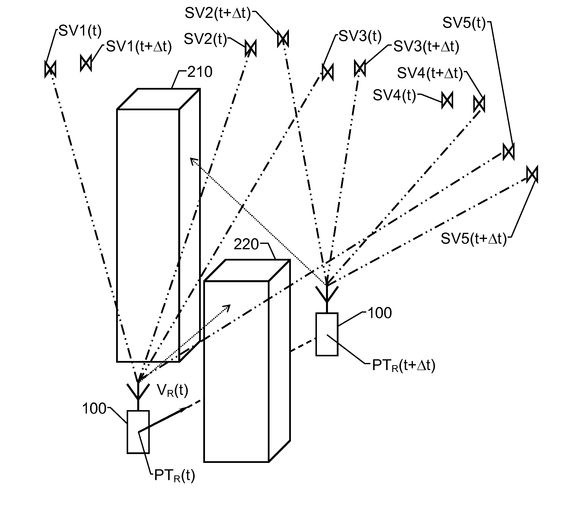
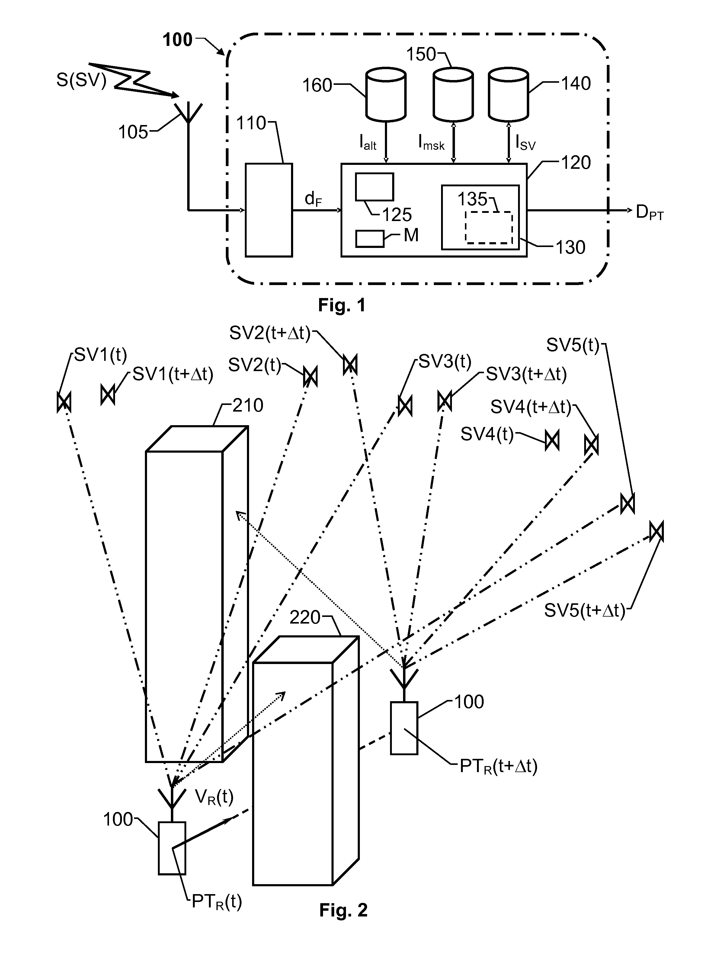
[0026]We refer initially to FIGS. 1 and 2, which show a block diagram of a GNSS receiver 100 according to one embodiment of the invention respective a group of signal sources and the receiver at two different positions / times.

[0027]The proposed receiver 100 is adapted to process radio signals S(SV) transmitted from an active set of signal sources and based thereon produce position / time related data DPT. Here, we assume that at a first position / time PTR(t), the active set includes a first signal source SV1, a second signal source SV2, a third signal source SV3 and a fifth signal source SV5. The receiver 100 has a tracking channel resource for each signal source in the active set, and the tracking channel resources are configured to process the radio signals S(SV) in parallel with respect to a real-time signal data rate of the signals.

[0028]The proposed receiver 100 includes a signal-source database 140, a signal-masking database 150 and a control unit 130. The signal-source database 1...


PUM


Abstract

A GNSS receiver (100) receives radio signals (S(SV)) transmitted from an active set of signal sources (SV1, SV2, SV3, SV5) and based thereon produces position / time related data (DPT). The receiver (100) has a tracking channel resource for each signal source (SV1, SV2, SV3, SV5) in the active set, and the tracking channel resources process the radio signals (S(SV)) in parallel with respect to a real-time signal data rate of the signals. The receiver (100) also includes a signal-source database (140), a signal-masking database (150) and a control unit (130). The signal-source database (140) describes the movements of the signal sources (SV1, SV2, SV3, SV4, SV5) over time relative to a given reference frame, and the signal-masking database (150) reflects, for positions (P) within a predefined geographic area, visibility / blockage to the sky with respect to a direct line of sight in terms of spatial sectors (M1(P), M2(P) M3(P)). The control unit (130) derives data describing a current position / time (PTR(t)) and a current velocity vector (VR(t)) for the receiver (100) based on the position / time related data (DPT); and derives an estimated visibility of the signal sources (SV1, SV2, SV3, SV5) in the active set at a second position / time (PTR(t+Δt)) representing an expected future position / time for the receiver (100) based on the signal-source and signal-masking databases (140; 150). If at least one signal source (SV1) in the active set is estimated not to be visible at the second position / time (PTR(t+Δt)), the control unit (130) initiates a modification of the active set aiming at replacing the at least one non-visible signal source (SV1) with at least one signal source (SV4) which, based on the signal-source and signal-masking databases (140; 150), is estimated to be visible at the second position / time (PTR(t+Δt)).

Description

THE BACKGROUND OF THE INVENTION AND PRIOR ART[0001]The present invention relates generally to reception and processing of spread spectrum signals in Global Navigation Satellite System (GNSS) receivers. More particularly the invention relates to a receiver according to the preamble of claim 1 and a method of operating a receiver according to the preamble of claim 10. The invention also relates to a computer program according to claim 17 and a computer readable medium according to claim 18.[0002]Many examples of GNSSs exist. Presently, the Global Positioning System (GPS; U.S. Government) is the dominant system; however alternative systems are expected to gain increased importance in the future. So far, the GLObal NAvigation Satellite System (GLONASS; Russian Federation Ministry of Defense) and the Galileo system (the European programme for global navigation services) constitute the major alternative GNSSs. Various systems also exist for enhancing the coverage, the availability and / or ...

Claims


Application Information

Patent Timeline
Patent Type & Authority Applications(United States)
IPC IPC(8): G01S19/28
CPCG01S19/28G01S19/22G01S19/258
Inventor REIDEVALL, MARTIN BORJESSONHAKANSON, MATS ROBINMITELMAN, ALEXANDER MICHAEL
Owner QUALCOMM TECH INT
Why Eureka
Try Eureka