Monolithic laser source using ring-resonator reflectors

a monolithic laser and reflector technology, applied in the field of laser sources, can solve the problems of high cost, difficult to achieve low-cost wdm laser sources, and difficult to implement wdm silicon-photonic,

Inactive Publication Date: 2012-07-26
ORACLE INT CORP
View PDF10 Cites 59 Cited by
  • Summary
  • Abstract
  • Description
  • Claims
  • Application Information

AI Technical Summary

Problems solved by technology

However, a suitable low-cost WDM laser source remains a challenge and poses an obstacle to implementing WDM silicon-photonic links
In particular, existing WDM lasers (such as those used to transmit optical signals in WDM telecommunications systems) are usually very expensive and are typically single-wavelength sources.
Because future WDM silicon-photonic links are expected to include thousands of optical channels (or more), the total cost of these WDM laser sources is likely to be prohibitive.
Furthermore, in order to reduce the tuning power of a WDM silicon-photonic link, the wavelengths output by the WDM laser source for each optical channel may need to have a very narrow line width (such as less than a few picometers), which can be difficult to achieve.
However, the yield and scaling of these laser arrays may make it difficult to obtain a low-cost laser source.
Nonetheless, because of their size, cost and power consumption, the resulting laser sources also have not achieved a low-cost solution for use in a WDM silicon-photonic link.
Furthermore, while a comb laser based on quantum dots has recently shown promise for transmitting wavelengths in the O band (1260-1360 nm), this laser source is not thought to be suitable for use in a WDM silicon-photonic link because of the limited availability of associated modulators and detectors.

Method used


Image

  • Monolithic laser source using ring-resonator reflectors
  • Monolithic laser source using ring-resonator reflectors
  • Monolithic laser source using ring-resonator reflectors

Examples


Embodiment Construction

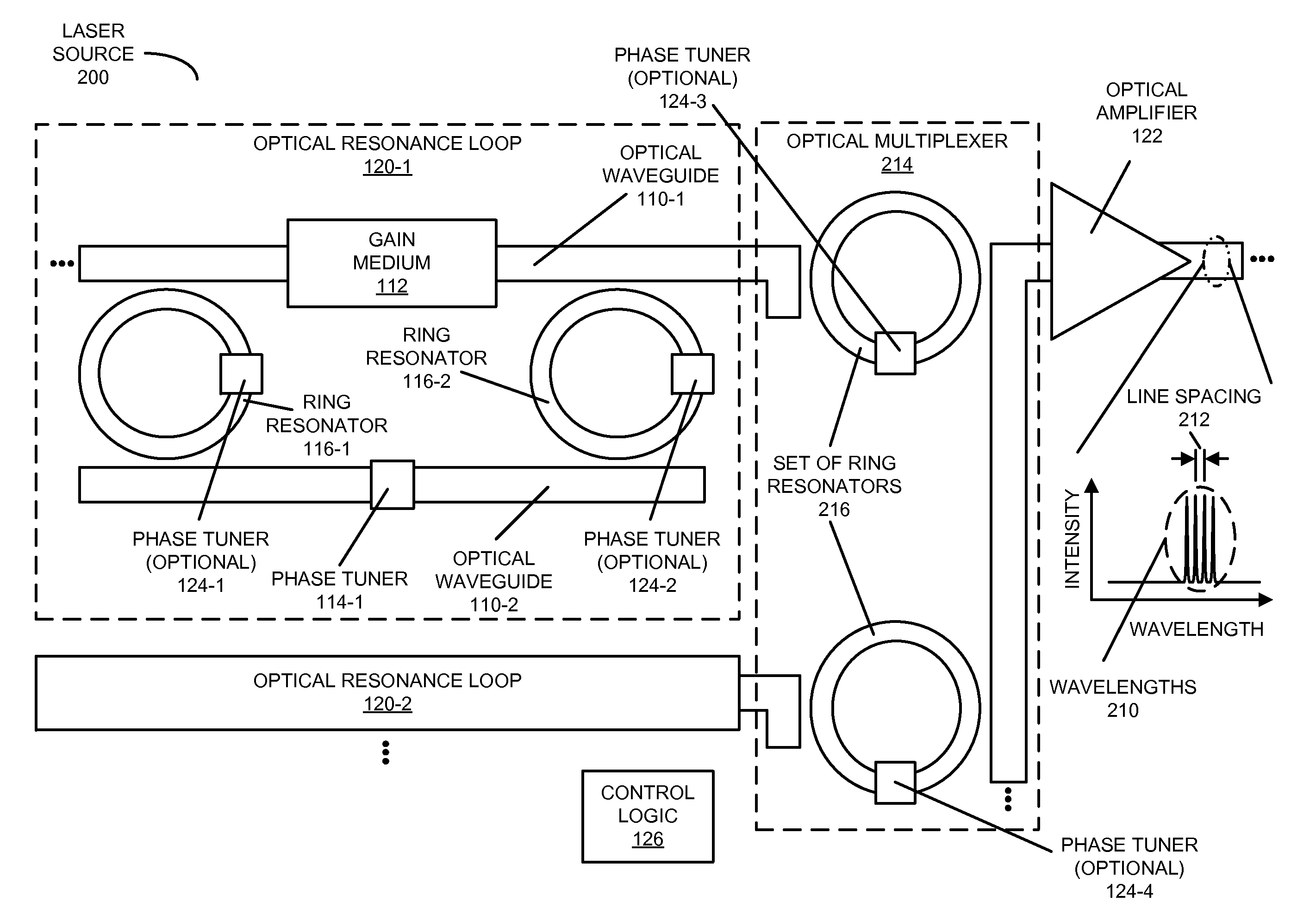
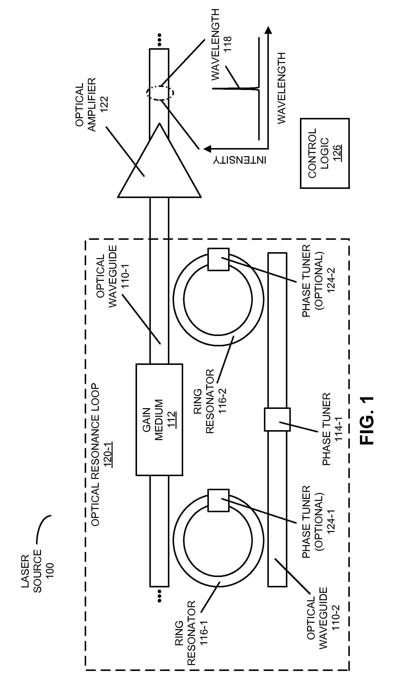
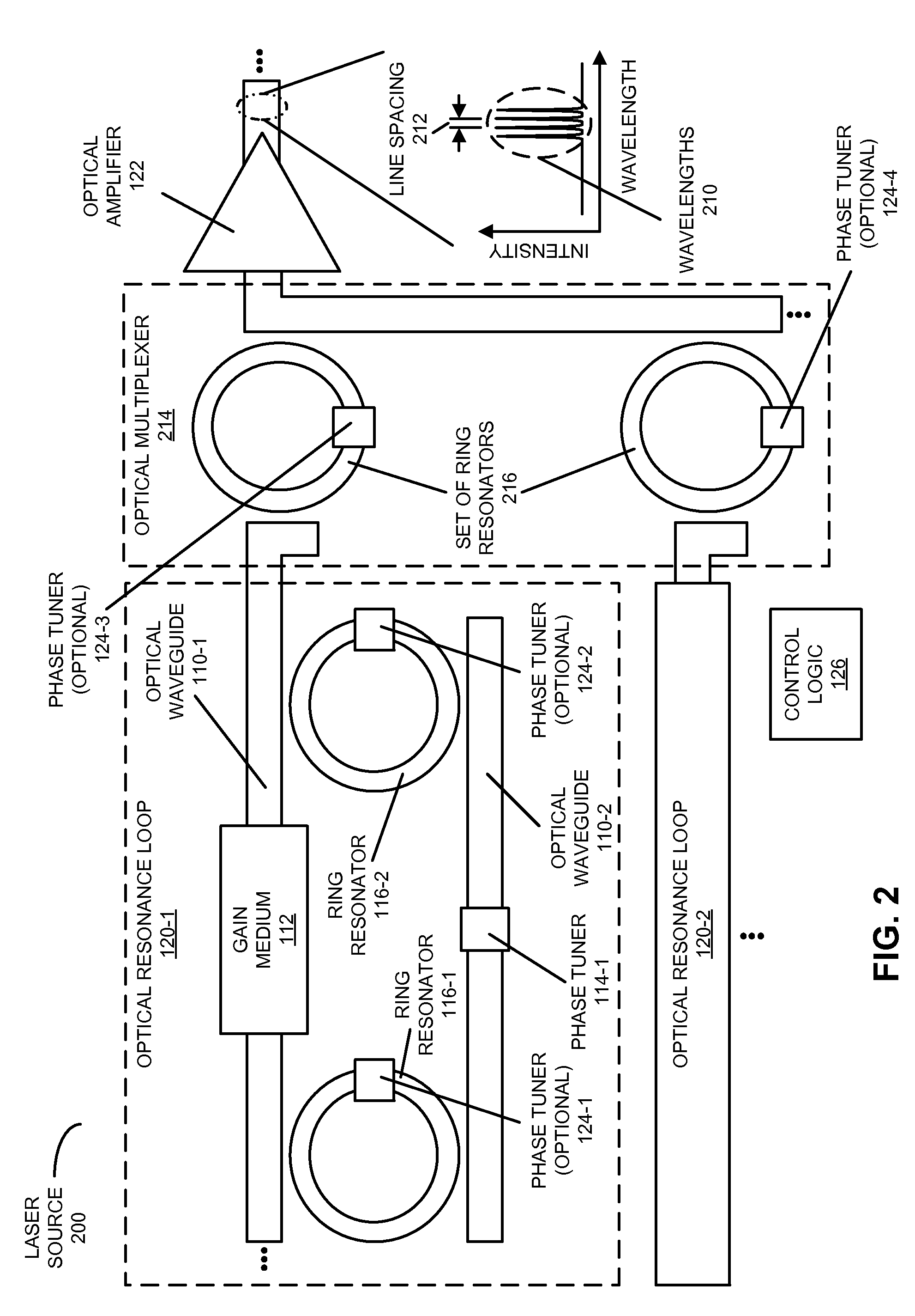
[0025]Embodiments of a laser source, a system that includes the multiple-wavelength laser source, and a technique for outputting an optical signal using the laser source are described. In the laser source, a first optical waveguide includes a gain medium, and a second optical waveguide includes a phase tuner which adjusts a phase value of the phase tuner to specify the wavelength of the laser source. Furthermore, the laser source includes a first ring resonator and a second ring resonator, which, respectively, are optically coupled to the first optical waveguide and the second optical waveguide at opposite ends of the laser source. In particular, coupling wavelengths of the first and second ring resonators may match at least a wavelength of the optical signal, thereby defining an optical resonance cavity in the laser source and selecting a laser mode of the laser source which is associated with the wavelength. Additionally, the laser source includes an optical amplifier that receive...


PUM


Abstract

In a laser source, a first optical waveguide includes a gain medium, and a second optical waveguide includes a phase tuner which adjusts a phase value of the phase tuner to specify the wavelength of the laser source. Furthermore, the laser source includes a first ring resonator and a second ring resonator, which, respectively, are optically coupled to the first optical waveguide and the second optical waveguide at opposite ends of the laser source. In particular, coupling wavelengths of the first and second ring resonators may match a wavelength of the optical signal, thereby defining an optical resonance cavity in the laser source and selecting a laser mode of the laser source which is associated with the wavelength. Additionally, the laser source includes an optical amplifier that receives and amplifies the optical signal output from the optical resonance cavity.

Description

GOVERNMENT LICENSE RIGHTS[0001]The United States Government has a paid-up license in this invention and the right in limited circumstances to require the patent owner to license others on reasonable terms as provided for by the terms of Agreement No. HR0011-08-9-0001 awarded by the Defense Advanced Research Projects Administration.BACKGROUND[0002]1. Field[0003]The present disclosure relates to techniques for communicating optical signals. More specifically, the present disclosure relates to a laser source that includes an optical resonance cavity defined by ring-resonator reflectors.[0004]2. Related Art[0005]Silicon photonics is a promising technology that can provide large communication bandwidth, low latency and low power consumption for inter-chip and intra-chip connections. In the last few years, significant progress has been made in developing low-cost components for use in inter-chip and intra-chip silicon-photonic connections, including: high-bandwidth efficient silicon modul...

Claims


Application Information

Patent Timeline
Patent Type & Authority Applications(United States)
IPC IPC(8): H01S5/06
CPCH01S5/021H01S5/02248H01S5/0261H01S5/50H01S5/06255H01S5/1032H01S5/1071H01S5/0612H01S5/142H01S5/02325
Inventor ZHENG, XUEZHEKRISHNAMOORTHY, ASHOK V.CUNNINGHAM, JOHN E.
Owner ORACLE INT CORP
Why Eureka
Try Eureka