Efficient heat exchange system for storing energy

a heat exchange system and energy storage technology, applied in the field of heat exchangers, can solve the problem that batteries are not optimal energy storage solutions, and achieve the effect of accelerating the heating of high operating temperature slurry

Active Publication Date: 2012-08-02
FSTP PATENT HLDG
View PDF3 Cites 6 Cited by
  • Summary
  • Abstract
  • Description
  • Claims
  • Application Information

AI Technical Summary

Benefits of technology

[0010]A waveguide network is coupled to the microwave energy source, and a high operating temperature slurry adapted for heating under microwave energy exposure is further provided. The waveguide network selectively directs energy from the microwave energy source to the slurry, with the permeable powdered metal-ceramic matrix being positioned coincident to the high operating temperature slurry, such that the permeable powdered metal-ceramic matrix accelerates the heating of the high operating temperature slurry when the electromagnetic energy is applied thereto.
[0011]The slurry is driven in a closed loop within the heat exchanger, and a working fluid is also circulated through the heat exchanger to transfer thermal energy from the slurry to the working fluid in order to effect phase change of the working fluid from a liquid to a high pressure gas. The high pressure gas is directed to an inlet of the engine in order to operate the engine, and electricity is produced under gas power from stored heat energy in the slurry until the slurry cools down to a temperature ineffective to cause the working fluid to change phase. A resonant cavity is formed about the heat exchanger, such that the slurry is co-located within the resonant cavity.

Problems solved by technology

However, batteries are not an optimal energy storage solution due to their poor charge time-to-discharge ratios and their toxicity upon disposal.

Method used


Image

  • Efficient heat exchange system for storing energy
  • Efficient heat exchange system for storing energy
  • Efficient heat exchange system for storing energy

Examples


Embodiment Construction

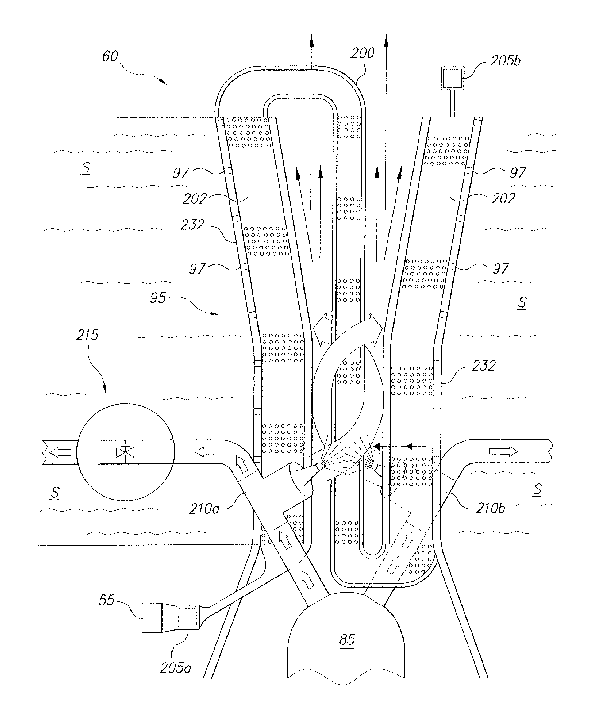
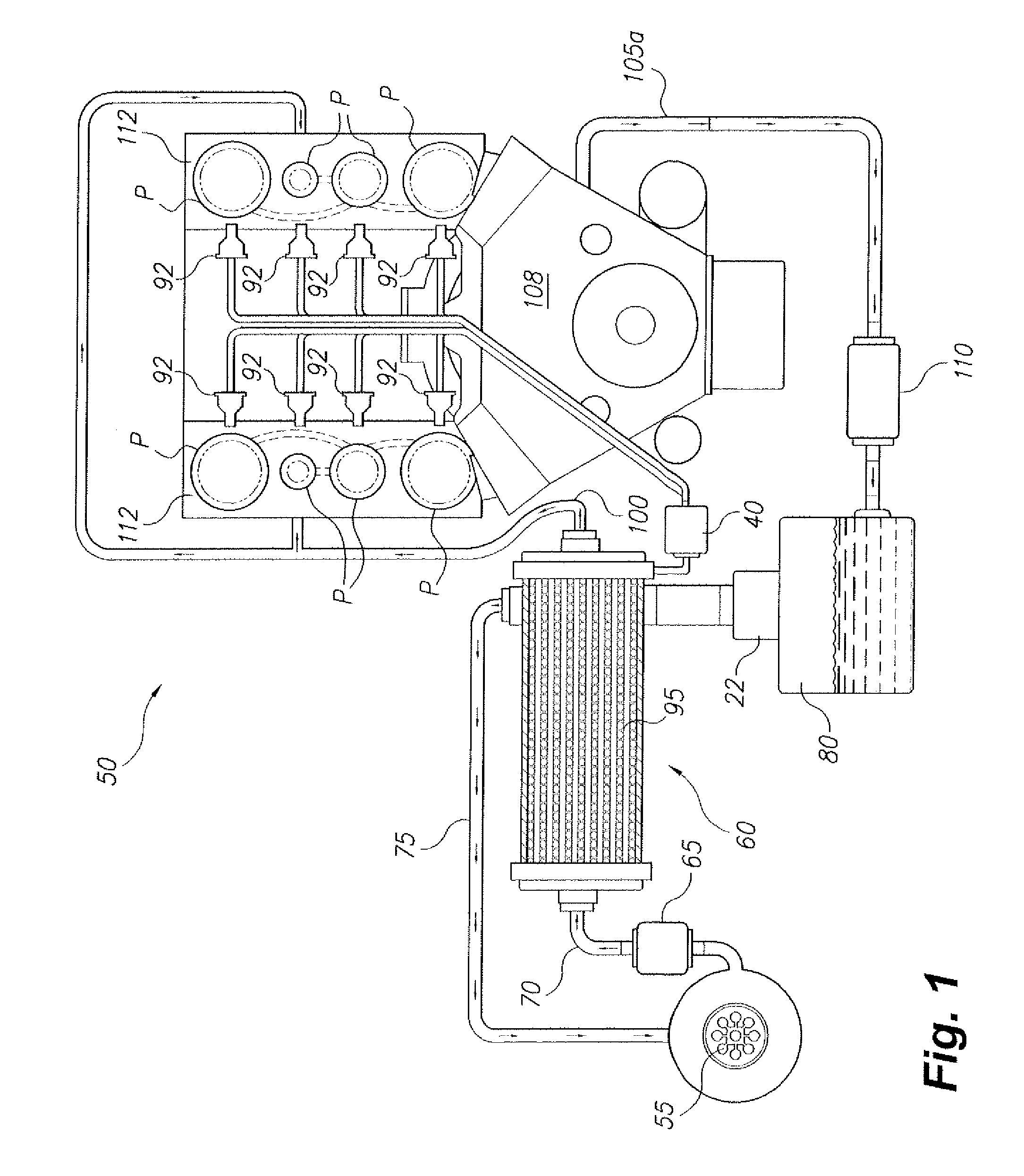
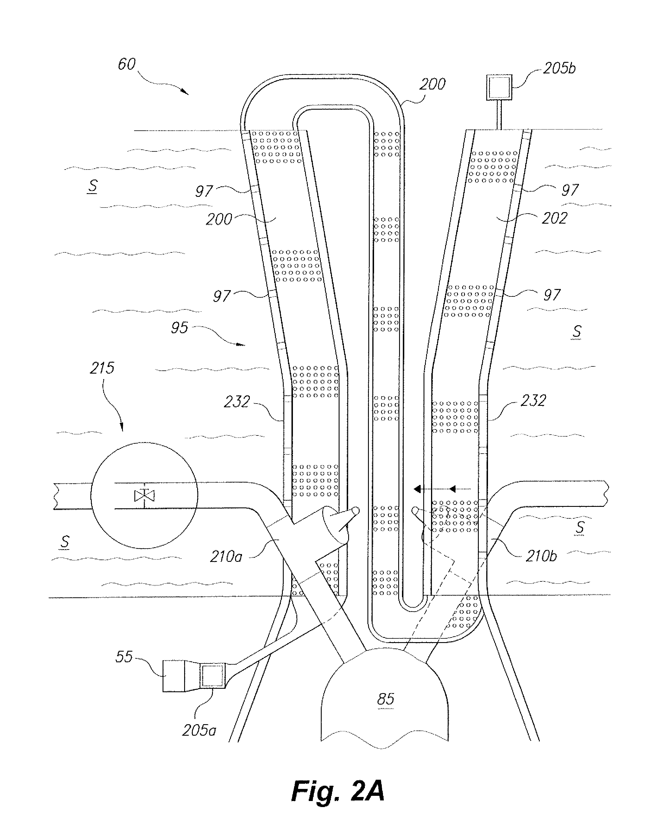
[0028]As shown if FIGS. 1, 2A and 2B, the present invention relates to an efficient heat exchange system, especially for use with a Rankine engine. The Rankine engine has a quickly rechargeable thermal energy bank with a slurry S circulating through an energy storage heat exchanger 60, such that the slurry S can be rapidly heated by electromagnetic energy in the form of microwave heating. The microwave energy may be supplied to the system via a network of waveguide / heat exchange gasifier tubes 200 and waveguide interconnections 205a and 205b (best seen in FIGS. 2A and 2B).

[0029]The microwave source may include, but is not limited to, at least one magnetron tube 55 that can be coupled to the waveguide network at waveguide interconnection 205a. The magnetron 55 can be charged by time and / or distance of desired operation; e.g., a commuter trip may be estimated for travel time or calculated by GPS or the like for distance. Under computer control, a high pressure fed, finely atomized wor...


PUM


Abstract

The efficient heat exchange system provides a rapidly rechargeable thermal energy storage bank operably connected to a heat engine capable of use in an electric power generation facility or in a vehicle. Microwave energy is supplied to the system via a network of waveguides. The thermal energy storage bank has a slurry in a heat exchanger capable of sustaining operation of the engine without requiring the microwave source. The slurry provides a mixture of powdered stainless steel and silicone oils functioning as the working fluid in the hot side of the heat exchanger. The slurry may be heated by plugging the system into standard AC power for a predetermined microwave heat charging duration. A closed, triple-expansion, reciprocating Rankine cycle engine capable of operating under computer control via a high pressure micro-atomized steam working medium is provided to propel the vehicle.

Description

CROSS-REFERENCE TO RELATED APPLICATION[0001]This application is a continuation-in-part of U.S. patent application Ser. No. 13 / 087,318, filed Apr. 14, 2011, which is a continuation-in-part of U.S. patent application Ser. No. 12 / 149,670, filed May 6, 2008, which claimed the benefit of U.S. Provisional Patent Application No. 60 / 929,012, filed Jun. 8, 2007. This application also claims the benefit of U.S. Provisional Patent Application Ser. No. 61 / 630,742, filed Dec. 19, 2011, U.S. Provisional Patent Application Ser. No. 61 / 629,912, filed Dec. 1, 2011, U.S. Provisional Patent Application Ser. No. 61 / 627,154, filed Sep. 19, 2011, and U.S. Provisional Patent Application Ser. No. 61 / 516,512, filed Apr. 5, 2011.BACKGROUND OF THE INVENTION[0002]1. Field of the Invention[0003]The present invention relates to heat exchangers, and particularly to a Rankine engine with an efficient heat exchange system that may be used, for example, to power a vehicle without expending non-renewable fuel (i.e., ...

Claims


Application Information

Patent Timeline
Patent Type & Authority Applications(United States)
IPC IPC(8): F28D17/00
CPCF01K3/00F22B27/16F01K25/10F01K15/02Y02E60/14B60K3/00F28D20/0034F28F23/00
Inventor FARKALY, STEPHEN J.
Owner FSTP PATENT HLDG
Why Eureka
Try Eureka