Lens concentrator system for semi-active laser target designation

Active Publication Date: 2012-08-02
RAYTHEON CO
View PDF35 Cites 4 Cited by
  • Summary
  • Abstract
  • Description
  • Claims
  • Application Information

AI Technical Summary

Benefits of technology

[0007]A semi-active laser (SAL) sensing system is provided that uses a lens concentrator system to pass received reflected laser light from an aperture to a detector. The lens concentrator system facilitates the use of SAL systems with different laser designator wavelengths to improve the performance of the SAL system.
[0008]In one embodiment, the lens concentrator system is formed from polymer having substantial optical clarity for electromagnetic radiation at wavelengths between 1.5 and 2.0 μm. In one such implementation, the lens concentrator system is formed from an amorphous fluoropolymer. The lens concentrator system formed from amorphous fluoropolymer facilitates the use SAL designators using different wavelengths than those in past SAL sensing systems. For example, the amorphous fluoropolymer lens concentrator system may facilitate the use lasers in SAL designators that are not detectable with detectors that are readily available to the general public, or in some countries due to export controls. Additionally, the amorphous fluoropolymer lens concentrator system may facilitate the use SAL designators that are less likely to cause eye injury.
[0009]Thus, when properly configured, the amorphous fluoropolymer lens concentrator system provides the optical path needed between the SAL sensing system aperture and the detector, and facilitates the use laser designator wavelengths that improve the performance of the SAL system.

Problems solved by technology

One issue in SAL systems is the wavelength (and thus frequency) of the laser beam used to designate targets.
In current implementations, SAL designators have been limited to wavelengths that are not desirable for all applications.
For example, because of limitations in current SAL sensing systems, current SAL designators have been limited to wavelengths for which inexpensive commercial detectors are readily available.
Unwanted detection of SAL use by third parties can lead to a variety of negative outcomes.

Method used


Image

  • Lens concentrator system for semi-active laser target designation
  • Lens concentrator system for semi-active laser target designation
  • Lens concentrator system for semi-active laser target designation

Examples


Embodiment Construction

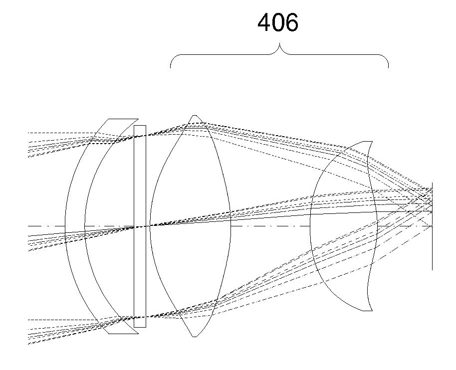
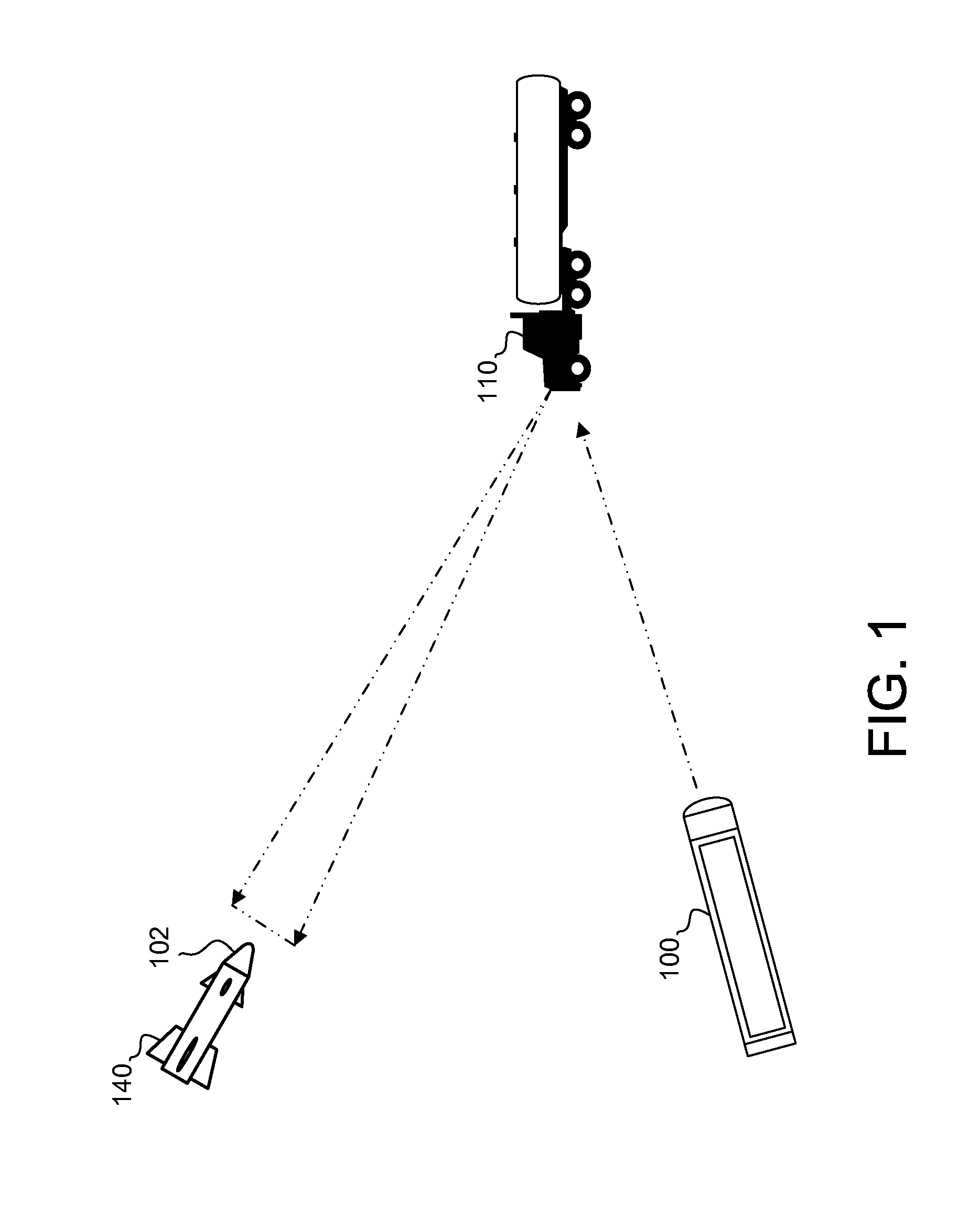
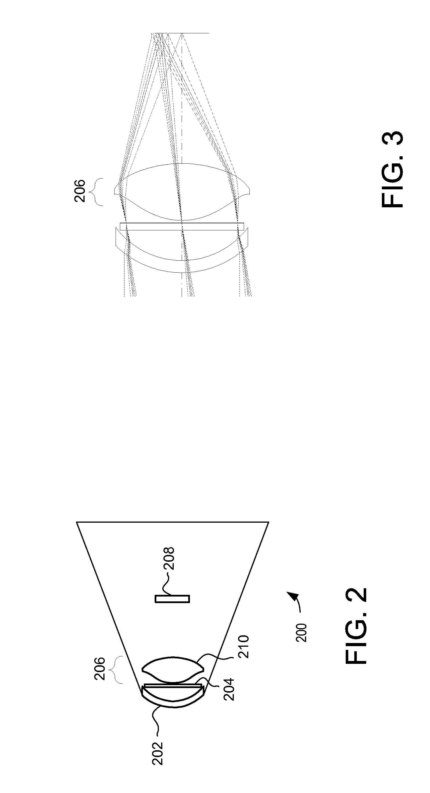
[0016]A semi-active laser (SAL) sensing system is provided that uses a lens concentrator system to pass received reflected laser light from an aperture to a detector. The lens concentrator system facilitates the use of SAL systems with different laser designator wavelengths to improve the performance of the SAL system.

[0017]In one embodiment, the lens concentrator system is formed from an amorphous fluoropolymer having optical clarity for electromagnetic radiation in a first wavelength range. The amorphous fluoropolymer lens concentrator system facilitates the use SAL designators using different wavelengths than those in past SAL sensing systems. For example, the use of amorphous fluoropolymer in a lens concentrator system facilitates the use of lasers in SAL designators that are not detectable with detectors that are readily available to the general public, or in some countries due to export controls.

[0018]When properly configured, the amorphous fluoropolymer lens concentrator syst...


PUM

PropertyMeasurementUnit
Lengthaaaaaaaaaa
Lengthaaaaaaaaaa
Wavelengthaaaaaaaaaa

Abstract

A semi-active laser (SAL) sensing system is thus provided that uses a lens concentrator system to pass received reflected laser light from an aperture to a detector. The lens concentrator system facilitates the use of SAL systems with different laser designator wavelengths to improve the performance of the SAL system. In one embodiment, the lens concentrator system is formed from polymer having substantial optical clarity for radiation having wavelengths between approximately 1.5 and approximately 1.65 μm. For example, the lens concentrator system may be formed from amorphous fluoropolymer. The lens concentrator system formed from amorphous fluoropolymer facilitates the use SAL designators using different wavelengths than those in past SAL sensing systems.

Description

TECHNICAL FIELD[0001]The present invention relates to guidance systems, including semi-active laser (SAL) designation of targets.BACKGROUND[0002]A variety of guidance systems are used in military applications. As one example, semi-active laser (SAL) designation is used in military systems to designate targets and guide a missile or other weapon to the target. In a typical SAL system, the operator of a SAL designator fires a narrow pulsed laser beam at a target. The SAL designator may be man-portable or carried by a designator aircraft such as an unmanned aerial vehicle (UAV).[0003]The laser beam fired by the SAL designator reflects off the target to provide a reflected spot that can be detected by a SAL sensing system. When the designated target is within range, the SAL sensing system starts processing the detected returns to detect the spot, acquire the designated target and to verify that the SAL designator was the source. The SAL sensing system includes processing equipment for g...

Claims


Application Information

Patent Timeline
IPC IPC(8): G01J5/08
CPCG02B1/041G02B19/0014G02B19/0047F41G7/2293F41G7/226C08L27/18
Inventor RONCONE, RONALD L.
Owner RAYTHEON CO
Why Eureka
Try Eureka