Battery voltage monitoring apparatus

a battery voltage and monitoring device technology, applied in battery/fuel cell control arrangement, instruments, transportation and packaging, etc., can solve the problem of different cut-off frequencies of different pathways, and achieve the effect of reducing the variation of cut-off frequencies

Inactive Publication Date: 2012-08-02
DENSO CORP
View PDF5 Cites 55 Cited by
  • Summary
  • Abstract
  • Description
  • Claims
  • Application Information

AI Technical Summary

Benefits of technology

[0019]According to the exemplary embodiment, there is provided a battery voltage monitoring apparatus of the type including an RC filter circuit disposed between a battery pack constituted of battery cells connected in series and a batt...

Problems solved by technology

Hence, the conventional battery voltage monitoring apparatus as described abo...

Method used


Image

  • Battery voltage monitoring apparatus
  • Battery voltage monitoring apparatus
  • Battery voltage monitoring apparatus

Examples


first embodiment

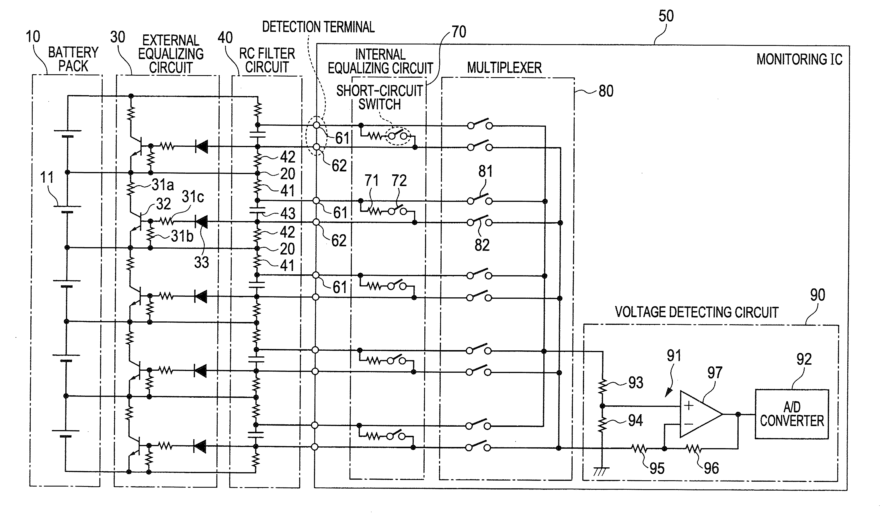
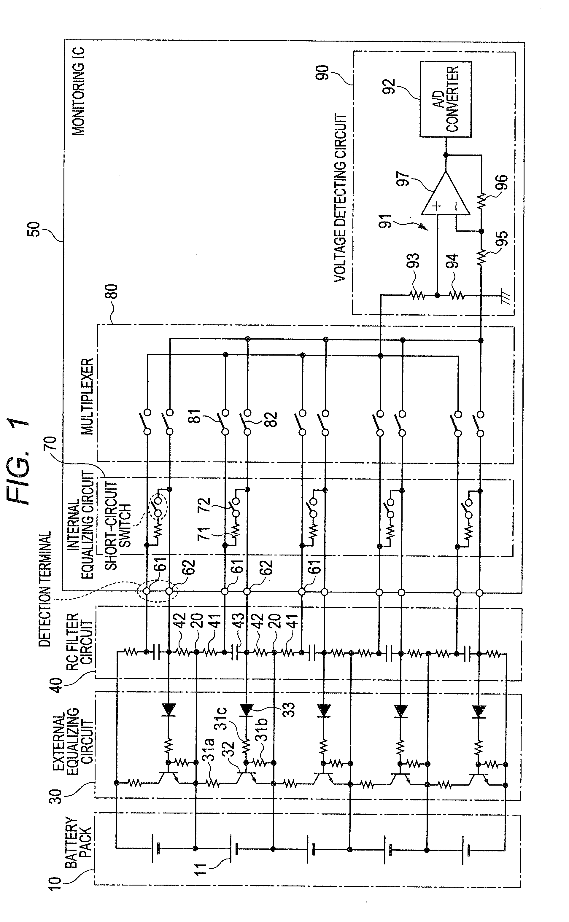
[0034]FIG. 1 is a diagram showing the overall structure of a battery voltage monitoring system including a battery voltage monitoring apparatus according to a first embodiment of the invention. The battery voltage monitoring system includes the battery voltage monitoring apparatus and a battery pack 10.

[0035]The battery pack 10 is constituted of a plurality of (five in this embodiment) battery cells 11 connected in series. Rechargeable lithium-ion batteries are used as the battery cells 11. The battery pack 10 is mounted on a hybrid vehicle or an electric vehicle as a power source for electrical loads such as an inverter or a motor, or a power source for electronic devices.

[0036]For each adjacent two of the battery cells 11, the wire connected between the negative electrode of one battery cell 11 and one of common terminals 20 provided in a later-described RC filter circuit 40 is used also as the wire connected between the positive electrode of the other battery cell 11 and another ...

second embodiment

[0091]Next, a second embodiment of the invention is described focusing on the difference with the first embodiment. The second embodiment differs from the first embodiment in the circuit structures of the external equalizing circuit 30 and the internal equalizing circuit 70.

[0092]FIG. 7 is a diagram showing the overall structure of a battery voltage monitoring system including a battery voltage monitoring apparatus according to the second embodiment of the invention. As shown in FIG. 7, the structure of the RC filter circuit 40, and the structures of the multiplexer 80 and the voltage detecting circuit 90 included in the monitoring IC 50 are the same as those of the first embodiment.

[0093]In the following description, of each adjacent two battery cells 11, the one on the lower voltage side is referred to as the first battery cell 12, and the one on the higher voltage side is referred to as the second battery cell 13. The paired detection terminals 61 and 62 for detecting the cell vo...


PUM


Abstract

The battery voltage monitoring apparatus has a structure in which, for each adjacent two of battery cells, the positive electrode of the battery cell on the higher voltage side and the negative electrode of the battery cell on the lower voltage side are commonly connected to a corresponding one of common terminals provided in an RC filter circuit. The common terminal is branched into a first branch connected to one end of a first resistor and a second branch connected to one end of a second resistor, the first resistor being connected to a corresponding one of positive side detection terminals at the other end thereof, the second resistor being connected to a corresponding one of negative side detection terminals at the other end thereof. A capacitor is connected across a corresponding one of pairs of the positive side and negative side detection terminals.

Description

[0001]This application claims priority to Japanese Patent Application No. 2011-19734 filed on Feb. 1, 2011, the entire contents of which are hereby incorporated by reference.BACKGROUND OF THE INVENTION[0002]1. Field of the Invention[0003]The present disclosure relates to a battery voltage monitoring apparatus including an RC filter circuit.[0004]2. Description of Related Art[0005]There is known a battery voltage monitoring apparatus capable of detecting a cell voltage of each of battery cells constituting a battery pack, as described, for example, in Japanese Patent Application Laid-open No. 2007-10580. The battery voltage monitoring apparatus described in this patent document is connected with positive and negative terminals of each battery cell to detect the cell voltage of each battery cell.[0006]Generally, as shown in FIG. 10, such a battery voltage monitoring apparatus is provided with a filter circuit as a noise countermeasure. The battery voltage monitoring apparatus shown in...

Claims


Application Information

Patent Timeline
IPC IPC(8): H02J7/00G01R31/36G01R31/58
CPCG01R31/026G01R31/362H02J7/0016G01R31/3658G01R31/3648B60L2240/547G01R31/396G01R31/3835B60L58/18B60L58/22G01R31/54Y02T10/70G01R31/58
Inventor MIZOGUCHI, TOMOMICHI
Owner DENSO CORP
Why Eureka
Try Eureka