Equalizer Circuit and Printed Circuit Board

Inactive Publication Date: 2012-08-02
HITACHI LTD
View PDF1 Cites 17 Cited by
  • Summary
  • Abstract
  • Description
  • Claims
  • Application Information

AI Technical Summary

Benefits of technology

[0010]On the other hand, since the technique described in JP Patent Publications (Kokai) No. 2006-254303 and No. 2008-294837 is configured to smooth the frequency characteristic with a passive equalizer made up of passive components, power consumption can be reduced more easily than in the techniques described in JP Patent Publications (Kokai) No. 2003-309461 and No. 5-83164 (1993). In JP Patent Publication (Kokai) No. 2006-254303, an inductor and a resistor are connected to the terminal end of an interconnection line to smooth the characteristic of the interconnection line with the frequency characteristic of the inductor. In JP Patent Publication (Kokai) No. 2008-294837, an equalizer circuit made up of a capacitor, a resistor, and an inductor is disposed in a driver for outputting a signal to an interconnection line, thereby smoothing the characteristic of the interconnection line.
[0012]The present invention has been made to solve the above described problems, and provides a low power consumption equalizer circuit, which can smooth the frequency characteristic of circuit in accordance with the characteristic of the interconnection path without changing components to be mounted for each circuit.

Problems solved by technology

The technique described in JP Patent Publication (Kokai) No. 2003-309461 requires addition of a circuit for performing a pre-emphasis processing to emphasize high frequency signals, and therefore power consumption increases for that part.
Since the technique described in JP Patent Publication (Kokai) No. 5-83164 (1993) also requires addition of an equalizer circuit by means of an active circuit, power consumption will increase.

Method used


Image

  • Equalizer Circuit and Printed Circuit Board
  • Equalizer Circuit and Printed Circuit Board
  • Equalizer Circuit and Printed Circuit Board

Examples


embodiment 1

Summary

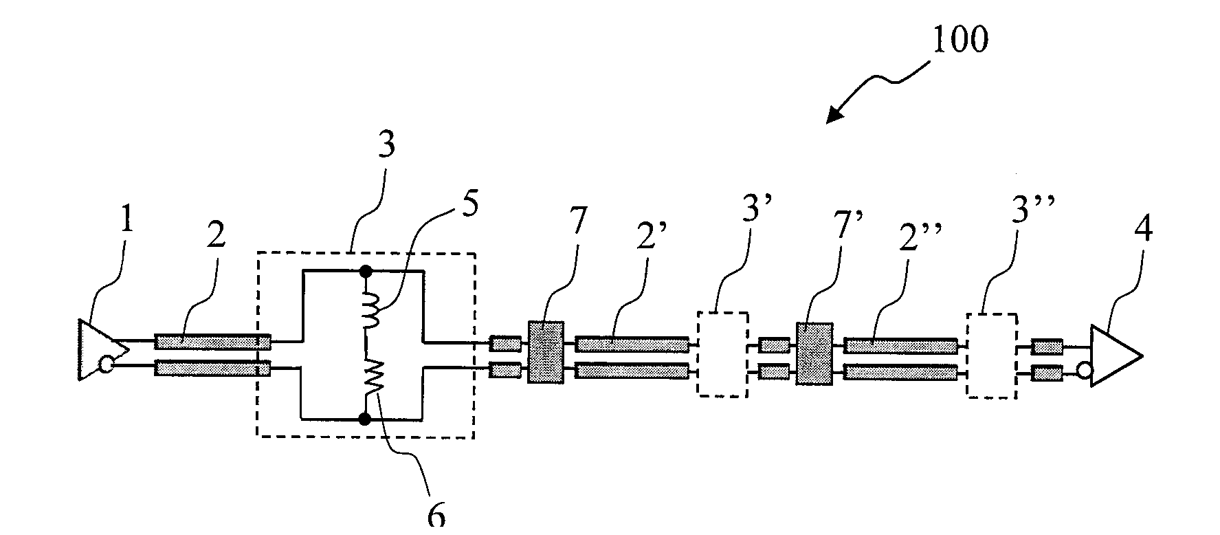
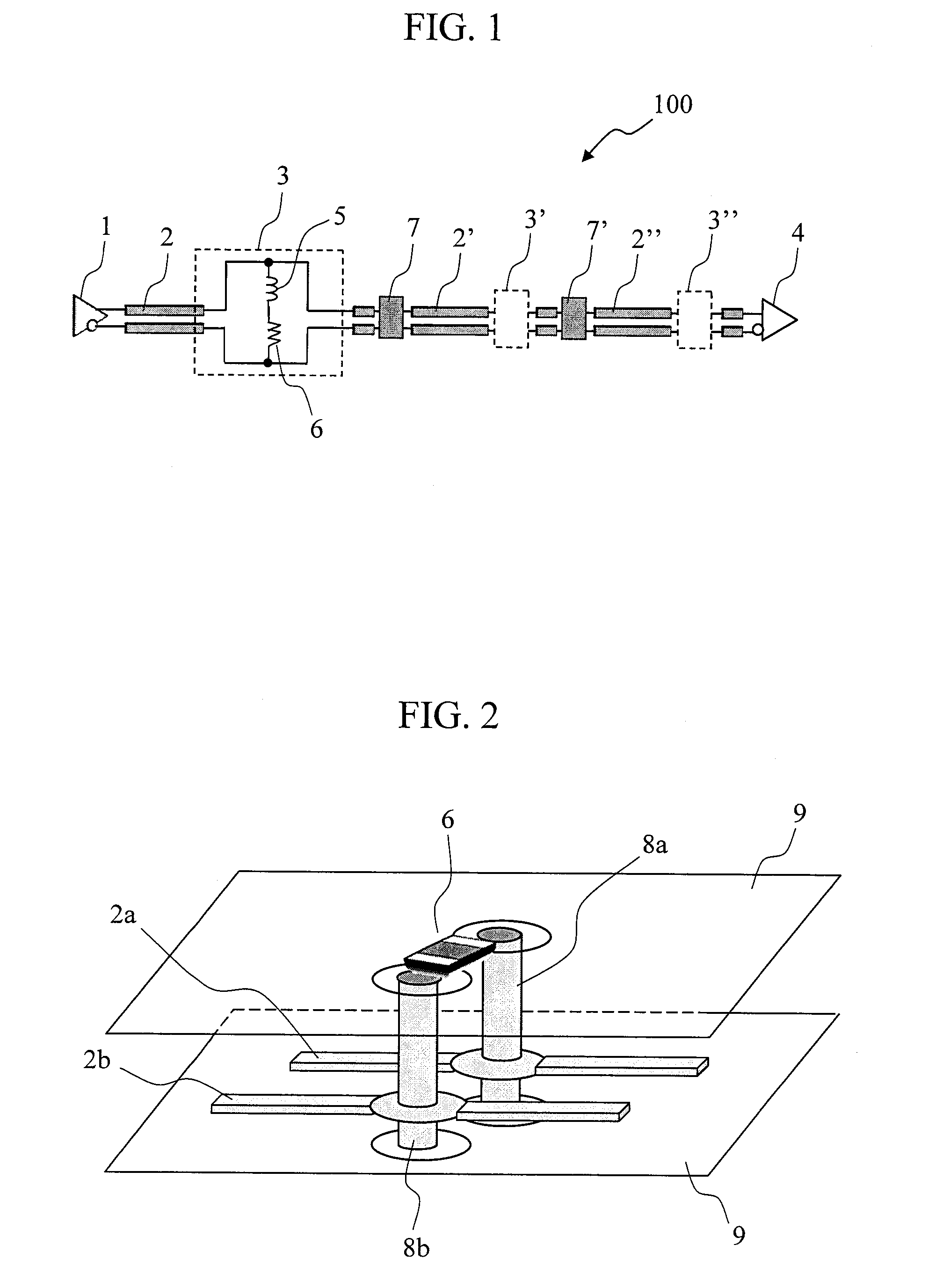
[0039]As described so far, the equalizer circuit 100 according to the present Embodiment 1 includes the passive equalizer 3 which is connected in parallel to the signal line 2, and the inductor 5 of the passive equalizer 3 is made up by using a conductor portion formed on the side face of the through-hole 8 which penetrates the printed circuit board 9. By adjusting the length of the through-hole 8, it is possible to adjust the inductance of the inductor 5 in accordance with the characteristic of the signal line 2. This eliminates the need of replacing the components of the passive equalizer 3 for each characteristic of the signal line 2, which is advantageous in terms of the flexibility in configuration, manufacturing period, cost, and the like.

Embodiment 2

[0040]FIG. 6 is a perspective view of the passive equalizer 3 included in the equalizer circuit 100 according to Embodiment 2 of the present invention. Since the configuration of the passive equalizer 3 is similar to that o...

embodiment 2

Summary

[0046]As so far described, in the equalizer circuit 100 according to the present Embodiment 2, the through-hole 8 is provided at a position which is apart from the extension line of the signal line 2 and where it does not intersect at right angles with the signal line 2, and the signal line 2 is configured to be diverted from its advancing direction in the vicinity of the through-hole 8 and to be brought into contact with the conductor portion. By this configuration, even when the size of the resistor 6 which is a chip component is larger than the disposition spacing of the signal line 2, it is possible to make up an equivalent circuit to that of FIG. 1.

embodiment 3

[0047]FIG. 7 is a perspective view of the passive equalizer 3 included in the equalizer circuit 100 according to Embodiment 3 of the present invention. Since the configuration of the passive equalizer 3 is similar to that of Embodiment 1 excepting the peripheral configuration thereof, hereafter, the configuration shown in FIG. 7 will be mainly described.

[0048]In FIG. 6 which is described regarding Embodiment 2, it is described that the through-holes 8a and 8b are connected by the electric wiring 10. While this electric wiring 10 in principle connects between the through-holes 8a and 8b in a linear fashion, a bypass wiring as shown in FIG. 7 may be adopted as needed. In this case, the length of the electric wiring 10 becomes longer than that in FIG. 6 and, as a result, the electric wiring 10 itself forms a significant inductance together with the conductor portion of the through-hole 8 as well.

[0049]Accordingly, when the length of the through-hole 8 is not sufficient, the electric wi...


PUM


Abstract

An equalizer circuit includes a passive equalizer having an inductor connected in parallel to a signal interconnection line, the inductor being made up of a conductor portion formed on a side face of a through-hole of a circuit board.

Description

CLAIM OF PRIORITY[0001]The present application claims priority from Japanese patent application JP 2011-016121 filed on Jan. 28, 2011, the content of which is hereby incorporated by reference into this application.BACKGROUND OF THE INVENTION[0002]1. Field of the Invention[0003]The present invention relates to an equalizer circuit for interconnecting an electrical signal, and a printed circuit board installed with the equalizer circuit.[0004]2. Background Art[0005]In recent years, as the performance of electronic instruments increases, the signal interconnection speed between electronic components such as LSI (Large Scale Integration) circuits installed in an electronic instrument has been approximately doubling every three years. Particularly, in a backplane used in large-volume data processing equipment such as a server and a rooter, etc., it is predicted that an interconnection speed of more than 25 Gbps which means a limit of electrical interconnection will be demanded in about t...

Claims


Application Information

Patent Timeline
IPC IPC(8): H04B3/14
CPCH04L25/03878H04B3/04H05K2201/086H05K1/0251H05K1/0233
Inventor MURAOKA, SATOSHI
Owner HITACHI LTD
Why Eureka
Try Eureka