Determining relative scan velocity to control ion implantation of work piece

a technology of relative scan velocity and ion implantation, which is applied in the field of ion implantation of work pieces, can solve the problems of difficult to tune the ion implant beam, the practical capabilities of the implant beam source, the mass analyzer, the accelerator, etc., and achieves the effect of reducing the cost of tuning the beam, reducing the cost of ion implantation, and reducing the cost of implantation

Inactive Publication Date: 2012-08-02
ADVANCED ION BEAM TECHNOLOGY INC
View PDF4 Cites 9 Cited by
  • Summary
  • Abstract
  • Description
  • Claims
  • Application Information

AI Technical Summary

Benefits of technology

[0009]In one exemplary embodiment, the implantation of a virtual work piece, which simulates or characterizes an actual work piece to be implanted by the ion implant beam, is simulated to select a relative velocity profile to be used in scanning the actual work piece with the ion implant beam of an ion implantation tool. A dose distribution across the virtual work piece is calculated based on an implant beam profile of an ion implantation tool and an initial relative velocity profile between the ion implant beam and the virtual work piece. A new relative velocity profile between the ion implant beam and the virtual work piece is then determined based on the calculated dose distribution and the relative velocity profile used in calculating the dose distribution. A new dose distribution across the virtual work piece is then calculated based on the implant beam profile and the new relative velocity profile. This new dose distribution is then analyzed to determine whether or not it meets one or more predetermined criteria such as dose uniformity or minimum dose concentration. If the new calculated dose distribution does not meet the criteria, a new relative velocity profile is determined based on the last calculated dose distribution and relative velocity profile, and a new dose distribution is then calculated based on this new relative velocity profile. The process of determining a new relative velocity profile and calculating a corresponding new dose distribution continues iteratively using the results of each prior calculation to determine a new relative velocity profile. The process terminates when a new relative velocity profile is obtained that yields a dose distribution across the virtual work piece that meets the one or more predetermined criteria. This new relative velocity profile is then stored as the selected relative velocity profile. In one embodiment, this new relative velocity profile may then be used to implant an actual work piece by scanning the actual work piece one or more times with the ion implant beam of an ion implantation tool using the new relative velocity profile to control the velocity with which the work piece is scanned with the ion implant beam.

Problems solved by technology

Tuning, however, is limited by the practical capabilities of the implant beam source, the mass analyzer, the accelerator, and the other components of an ion implantation tool.
It is sometimes, therefore, difficult to tune the ion implant beam to obtain the desired shape and current distribution, and time spent tuning the beam can be costly both in wasted implantation time and wasted ion implantation tool operating expenses.
This approach, however, results in wasting the portion of the ion implant beam that does not get implanted as it lands outside the dimensions of the circular work piece.
It has been unclear, however, how to efficiently determine an optimal relative scan velocity profile defining the velocity with which the work piece should be scanned relative to the ion implant beam to obtain a desired dose distribution.

Method used


Image

  • Determining relative scan velocity to control ion implantation of work piece
  • Determining relative scan velocity to control ion implantation of work piece
  • Determining relative scan velocity to control ion implantation of work piece

Examples


Embodiment Construction

[0024]The following description is presented to enable a person of ordinary skill in the art to make and use the various embodiments. Descriptions of specific devices, techniques, and applications are provided only as examples. Various modifications to the examples described herein will be readily apparent to those of ordinary skill in the art, and the general principles defined herein may be applied to other examples and applications without departing from the spirit and scope of the various embodiments. Thus, the various embodiments are not intended to be limited to the examples described herein and shown, but are to be accorded the scope consistent with the claims.

Overview of Process for Determining Velocity Profile

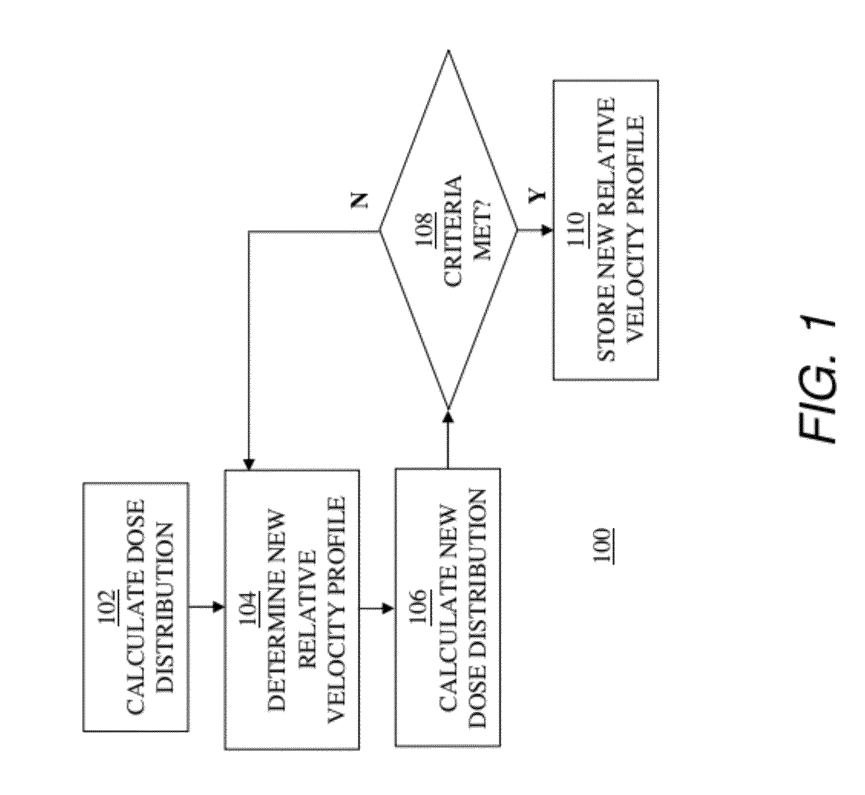
[0025]To illustrate the process described in detail below, FIG. 1 is provided depicting an exemplary process 100 for determining a selected relative velocity profile to be used in scanning a work piece with an ion implant beam. As an overview, the following brief descr...


PUM

PropertyMeasurementUnit
diameteraaaaaaaaaa
thicknessaaaaaaaaaa
diameteraaaaaaaaaa

Abstract

To select a relative velocity profile to be used in scanning an actual work piece with an ion implant beam of an ion implantation tool, the implantation of a virtual work piece is simulated. A dose distribution is calculated across the virtual work piece based on an implant beam profile and a relative velocity profile. A new relative velocity profile is then determined based on the calculated dose distribution and the relative velocity profile used in calculating the dose distribution. A new dose distribution is then calculated using the new relative velocity profile. A new relative velocity profile is determined and a corresponding new dose distribution is calculated iteratively until the new dose distribution meets one or more predetermined criteria. The new relative velocity profile is stored as the selected relative velocity profile when the new dose distribution meets the one or more predetermined criteria.

Description

BACKGROUND[0001]1. Field[0002]This application relates generally to ion implantation of a work piece, and more specifically to controlling the dose distribution across a work piece by simulating the implantation dose distribution across the work piece and modifying the relative scan velocity profile used in simulation and subsequent implantation.[0003]2. Related Art[0004]Dopant implantation is used to introduce conductivity-altering impurities, such as ions, into a work piece, such as a silicon wafer, a semiconductor plate, or a glass plate. The impurity material to be implanted may be ionized in an ion source and then separated in a mass analyzer to form an ion implant beam with ions of a specific charge-to-mass ratio. The ion implant beam may then be accelerated or otherwise modified before being directed to the work piece. The charged ions strike the surface and then penetrate into the work piece so that a desired conductive region is formed. Because the work piece surface area i...

Claims


Application Information

Patent Timeline
Patent Type & Authority Applications(United States)
IPC IPC(8): C23C14/48G06G7/62G06F17/10B05C11/00
CPCH01J37/3171H01J2237/31703H01J2237/304
Inventor SHEN, CHENG-HUIWAN, ZHIMIN
Owner ADVANCED ION BEAM TECHNOLOGY INC
Why Eureka
Try Eureka