Systems, apparatus, and methods of a solar energy grid integrated system with energy storage appliance

Active Publication Date: 2012-08-02
SUNVERGE ENERGY
View PDF28 Cites 95 Cited by
  • Summary
  • Abstract
  • Description
  • Claims
  • Application Information

AI Technical Summary

Benefits of technology

[0008]The embodiment of the SEGIS-ES™ is designed in such a way as to be located outside of a residence or commercial structure and to be of a form factor that coincides with electric and gas utility working space (siting) requirements of being less than 42 inches in depth when the SEGIS-ES™ enclosure door is open, and less than 18 inches in depth when the door is closed. Furthermore, in some embodiments the enclosure is no wider than 24 inches. Additionally, in some embodiments, multiple enclosures being 18 inches deep and 24 inches wide can be mechanically coupled together. The enclosure door, when in the open position, is made to be removable without the necessity of any tools. A three point padlockable latching mechanism equipped with a security pentahead bolt is additionally provided to restrict non-authorized personnel from opening the enclosure

Problems solved by technology

These technologies are herein referred to as “distributed energy sources.” Distributed energy sources have been deployed only to a very limited extent for reasons of cost, convenience, and a lack of harmonized grid inter-connection standards.
As a result, residential and commercial power storage and supply devices are typically very large and cumbersome.
Unfortunately, the use of alternative energy sources in conjunction with such power storage and supply device systems has been limited primarily because of cost and convenience and communications standards.
At present there are significant challenges to an individual's or building owner's installation of renewable energy technologies.
In addition, if the power generated in excess of requirements on the premise is to be resold, utilities impose additional requirements for co

Method used


Image

  • Systems, apparatus, and methods of a solar energy grid integrated system with energy storage appliance
  • Systems, apparatus, and methods of a solar energy grid integrated system with energy storage appliance
  • Systems, apparatus, and methods of a solar energy grid integrated system with energy storage appliance

Examples


Embodiment Construction

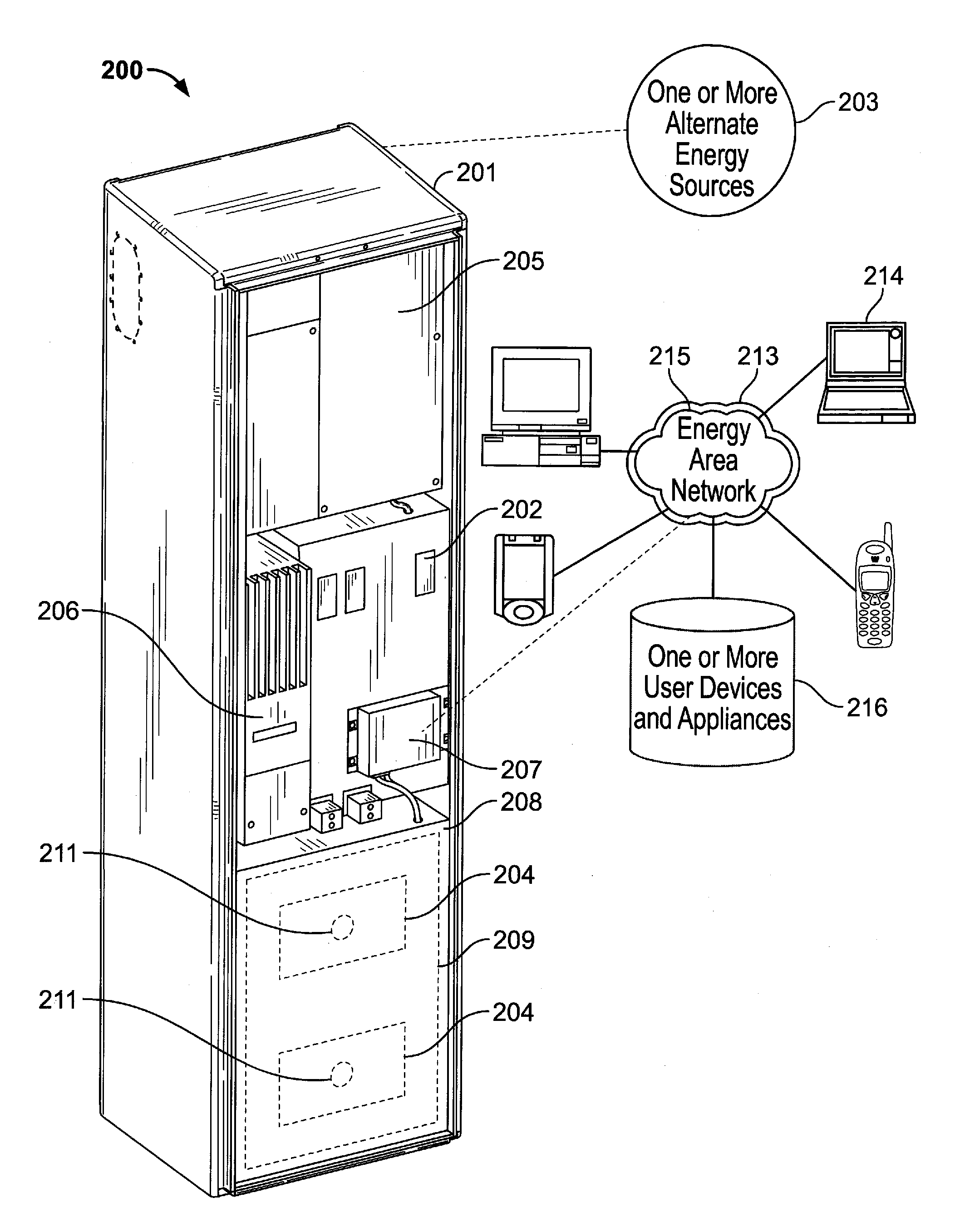
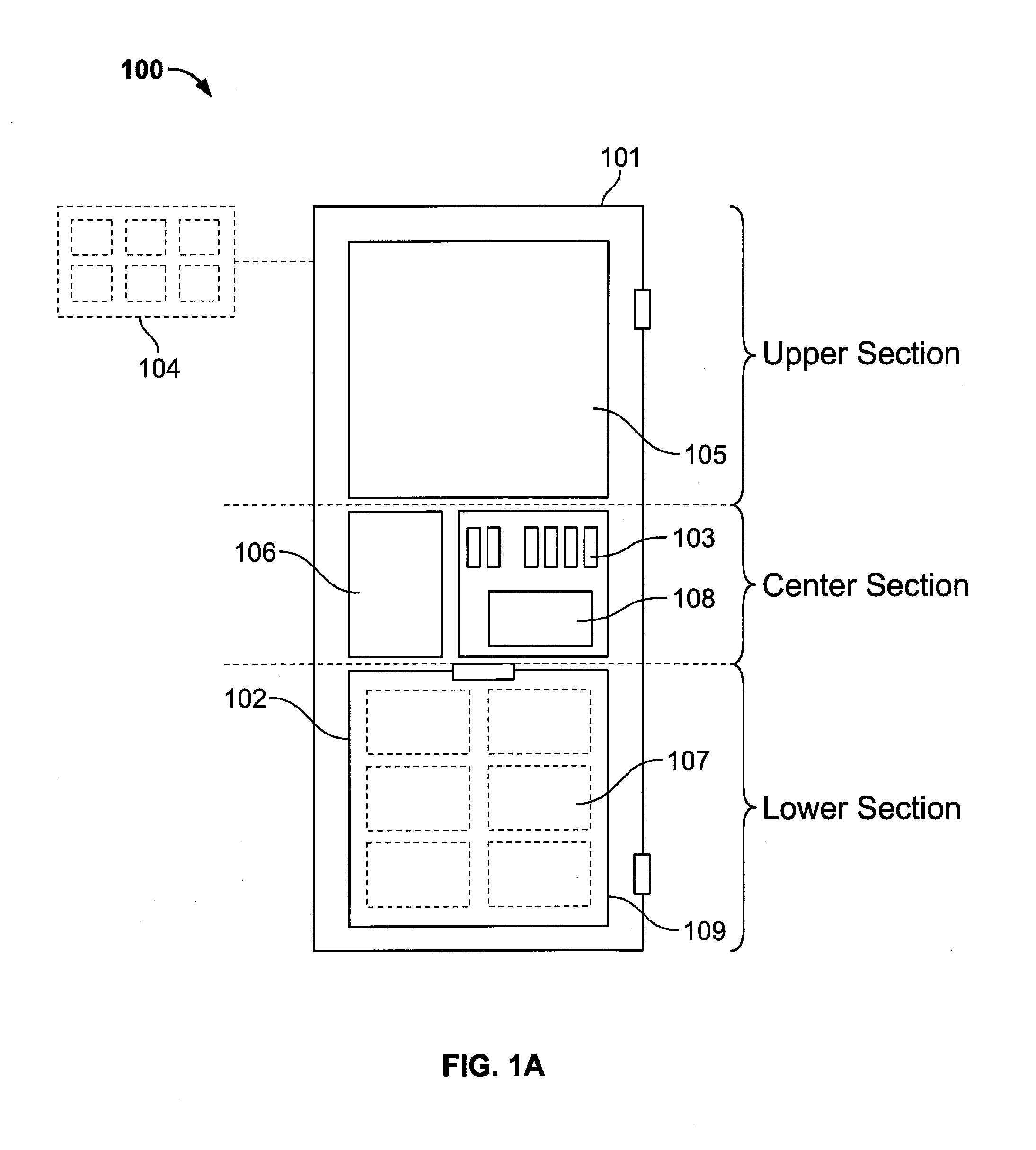
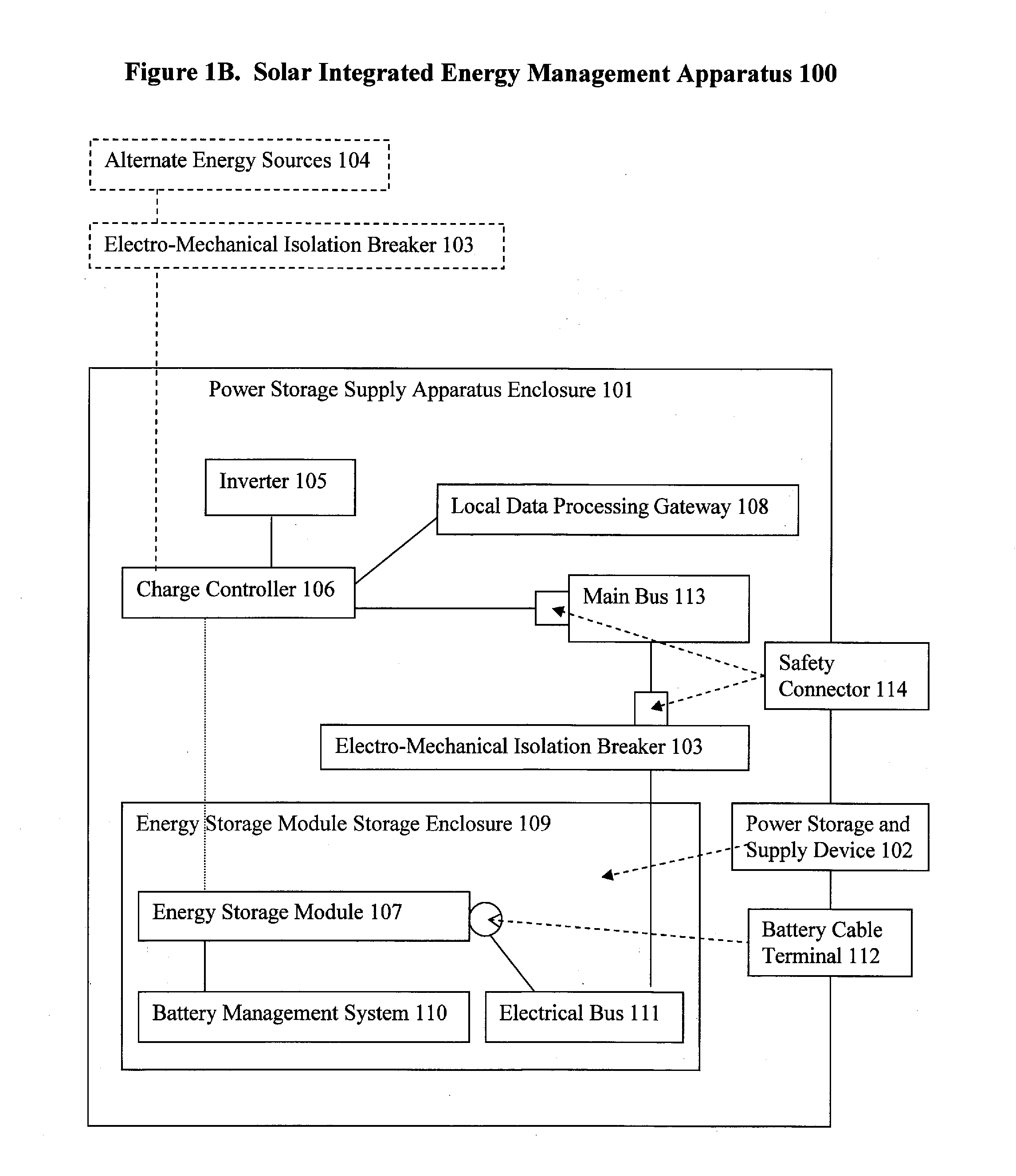
[0092]The present invention is directed to a device the present invention is directed towards a system, method, and device for integrating distributed energy sources, energy storage, and balance of system components into a single device with systems and control for monitoring, measuring, and conserving power generated on the premise, the resale of power to a utility, power generated from distributed energy storage (e.g., batteries) and distributed energy sources (e.g., solar panels). Moreover, the device is minimally invasive, modular, and retains power-generating capacity, which is combined with load management and energy storage to provide energy at or near the point of consumption.

[0093]The present invention can be further illustrated as a device that integrates the necessary components into a tamper resistant, utility grade, minimally invasive enclosure designed for outdoor applications, keeping unauthorized personnel from accessing the necessary components, and placed within th...


PUM


Abstract

A system, method, and apparatus for integrating distributed energy sources, energy storage, and balance of system components into a single device with systems and control for monitoring, measuring, and conserving power generated on the premise. A data processing gateway, hybrid inverter/converter and charge controller provide flexibility in the multi-voltages, output capacities, and photovoltaic array sizes coupled to the apparatus and system. The system and apparatus may be used in various commercial and residential applications. A user may store energy provided by one or more alternate energy sources coupled to an energy storage module. The system provides a compact enclosure that fits within a utility workspace and enclosures that can be mechanically coupled together, placed in parallel or in a series. A method, computer implemented apparatus, computer readable medium, computer implemented method and a system for monitoring energy consumption, selling energy back to a utility company and peak shaving are also provided.

Description

BACKGROUND[0001]The present invention relates generally to distributed energy storage and power management, and more particularly to a fully integrated system, method, and device for the controlling, monitoring, measuring, and conserving distributed power generated on the premise, the resale of distributed power to a utility, and power generated from distributed energy storage (e.g., batteries) and distributed renewable energy sources (e.g., solar panels). Moreover, the invention is minimally invasive, modular, and retains power-generating capacity, which is combined with load management and energy storage to provide energy at or near the point of consumption.[0002]The appliance described herein includes a lockable NEMA, or 3R contaminate or corrosion resistant enclosure which houses a plurality of devices for accomplishing localized and remote control electrical energy management for electrical loads sited at the appliance location. Additionally, the devices may be controlled to pr...

Claims


Application Information

Patent Timeline
IPC IPC(8): G05B15/00G06F13/14
CPCG05B15/02Y02B10/14G06F1/26Y02B10/10
Inventor SANDERS, DEAN
Owner SUNVERGE ENERGY
Why Eureka
Try Eureka