Apparatus and method for sample preparation

a sample and apparatus technology, applied in the field of sample preparation, can solve the problems of manual sample switchover after each etching operation, low equipment capacity utilization, and the like, and achieve the effects of minimizing reducing the number of sample switchovers, and improving equipment capacity utilization

Active Publication Date: 2012-08-09
LEICA MICROSYSTEMS GMBH
View PDF2 Cites 8 Cited by
  • Summary
  • Abstract
  • Description
  • Claims
  • Application Information

AI Technical Summary

Benefits of technology

[0007]It is an object of the invention to eliminate the disadvantages known from the existing art. The intention is in particular to achieve, with the invention, better equipment capacity utilization and thus greater cost-effectiveness, and to minimize the number of sample switchovers.
[0009]Thanks to the arrangement according to the present invention in one common vessel, aeration and opening of portions of the unit, e.g. the vacuum chamber, after each completed sample preparation is no longer necessary. That operation can be carried out only after all the samples have been completely prepared by ion beam etching. Because the positioning arrangements are arranged in one common vessel, the samples mounted thereon can be prepared successively with no need to break the vacuum. Non-use times are also significantly decreased, since capacity utilization of the ion beam etching unit over a longer period of time (e.g. overnight) is possible with no need for manual intervention by an operator for sample switchover.
[0011]Sample preparation by means of ion beam etching occurs preferably sequentially. It is furthermore possible, after a first preparation operation on each sample in a first run, to carry out a second or further preparation run on all or selected samples with no need for a manual sample switchover that includes aeration and opening of portions of the unit. In the context of the processing of heat-sensitive samples, for example, a need often exists for inserting pauses during ion beam etching in order to reduce stress on the sample. Thanks to the invention, heat-sensitive samples can therefore be switched into the waiting position in order to insert the pause, and preparation thereof can then be completed in a second or further preparation run. For certain applications it may be necessary to cool heat-sensitive samples that are in the waiting position. Cooling apparatuses for ion beam etching units are known to one skilled in the art. For certain samples it may also be necessary, subsequently to the ion beam etching operation that is usually carried out with a high-energy ion beam, to process the sample again briefly using a lower-energy ion beam. This processing with a lower-energy ion beam produces a cleaning effect on the previously exposed sample surface. Thanks to the invention, the possibility exists of processing a larger number of samples in any sequence with different preparation parameters.
[0013]In a preferred embodiment, the sample stage encompasses a turntable rotatable about a rotation axis, the positioning arrangements preferably being arranged on the rotatable turntable at identical angular offsets from one another, and the positioning arrangements being preferably sequentially orientable toward the ion beam by rotation of the turntable. Rotation of the turntable thus causes the positioning arrangements, with the samples fastened therein, to be switched respectively into the processing position or the waiting position. This embodiment is particularly compact and moreover has the advantage of accommodating a large number of positioning arrangements on the sample stage in space-saving fashion. In a first sub-variant in the manner of a horizontal turntable or sample carousel, the rotation axis of the turntable is oriented substantially vertically. In a second sub-variant in the manner of a vertical turntable, the rotation axis of the turntable is oriented substantially horizontally.
[0017]During the ion beam etching process, material is continuously removed by means of the ion beam from the sample located in the processing position. The risk exists in this context that these material particles may settle onto the samples located in the waiting position and consequently contaminate them, thereby possibly impairing the quality of the samples. It is therefore highly advantageous, in order to protect the positioning arrangements facing away from the ion beam from contamination, that according to the present invention, as mentioned above, protective dividers are arranged between positioning arrangements. With regard to the material nature of the protective divider, it is important that it be produced from a vacuum-compatible material that is easy to clean. Vacuum-compatible materials of this kind are known to one skilled in the relevant art. Because the protective divider is also at least partly exposed to the ion beam during the ion beam etching operation, it should be a material having a very low etching rate in order to minimize erosion. Hard metals, in particular steel, have proven particularly advantageous in practical use.

Problems solved by technology

The ion beam etching units known from the existing art and currently on the market have the disadvantage that a manual sample switchover is necessary after each etching operation.
Sample switchovers of this kind are time-consuming, and result in low equipment capacity utilization, low sample throughput, and consequently poor cost-effectiveness.
It is furthermore impossible to utilize the capacity of such apparatuses over a long period of time (e.g. overnight) without requiring a manual sample switchover by an operator.
In addition, as a result of aeration, each sample switchover represents an opportunity for contamination with airborne particles, requiring that the equipment be serviced at shorter time intervals.

Method used


Image

  • Apparatus and method for sample preparation
  • Apparatus and method for sample preparation
  • Apparatus and method for sample preparation

Examples


first embodiment

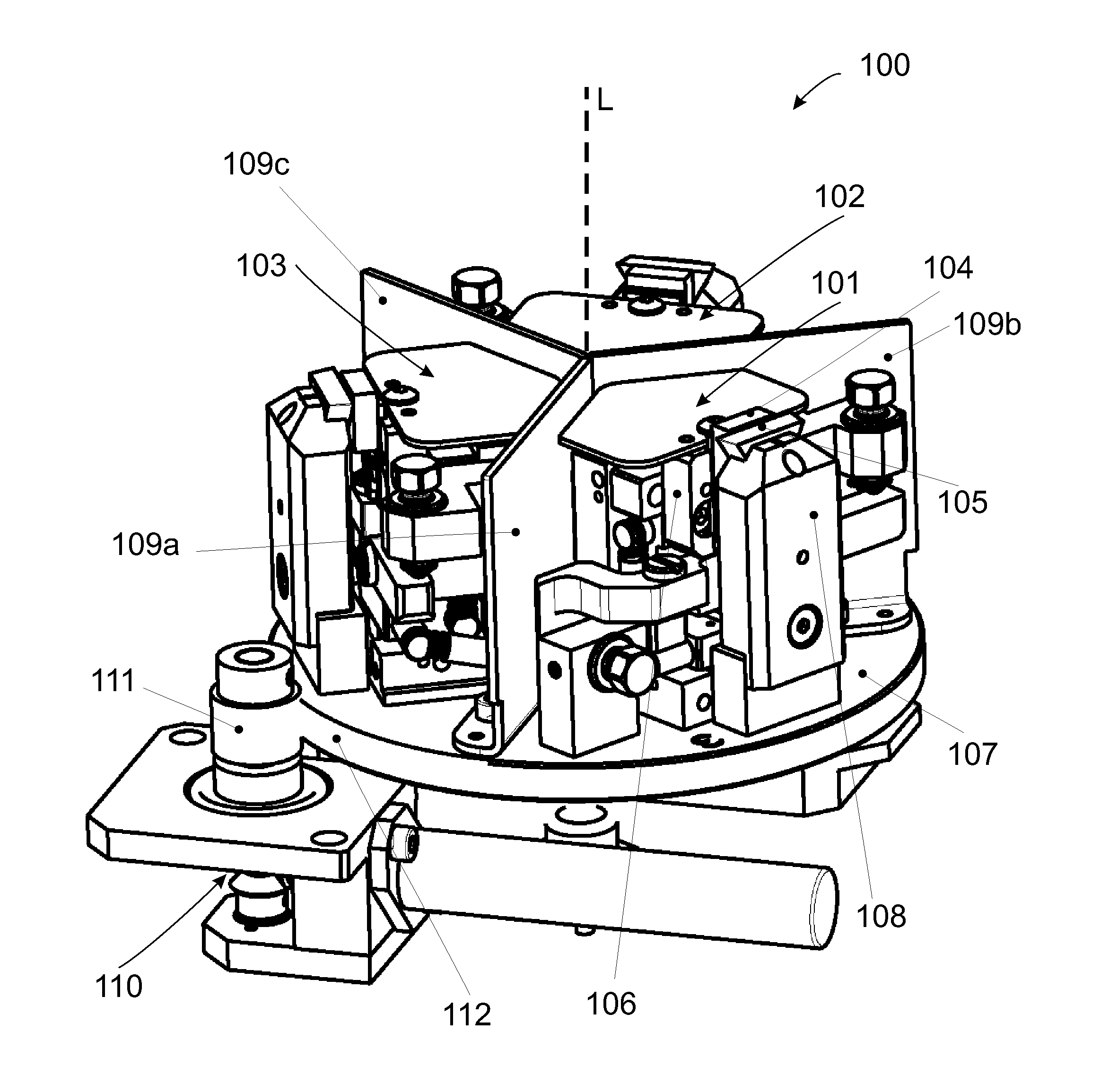
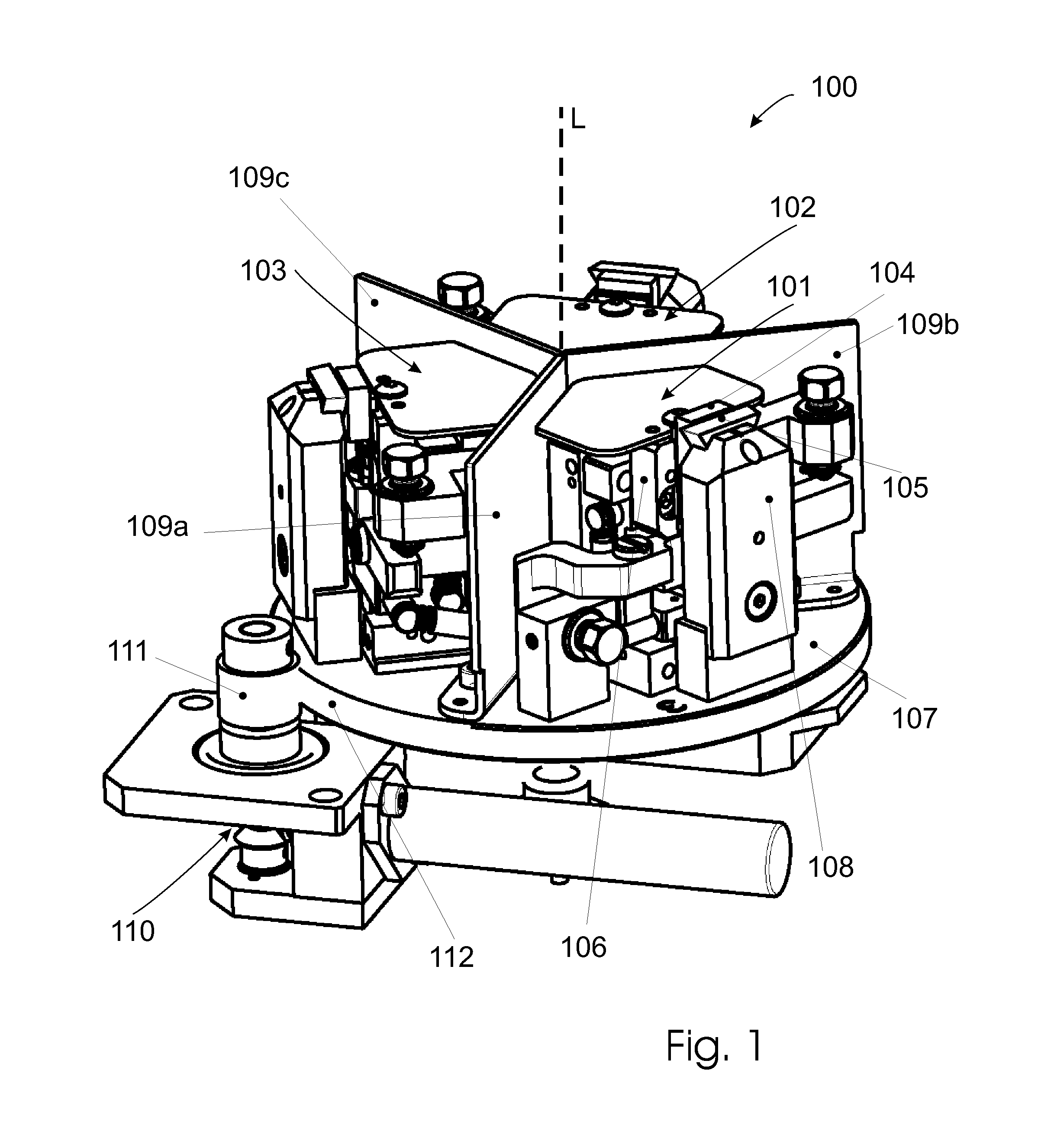
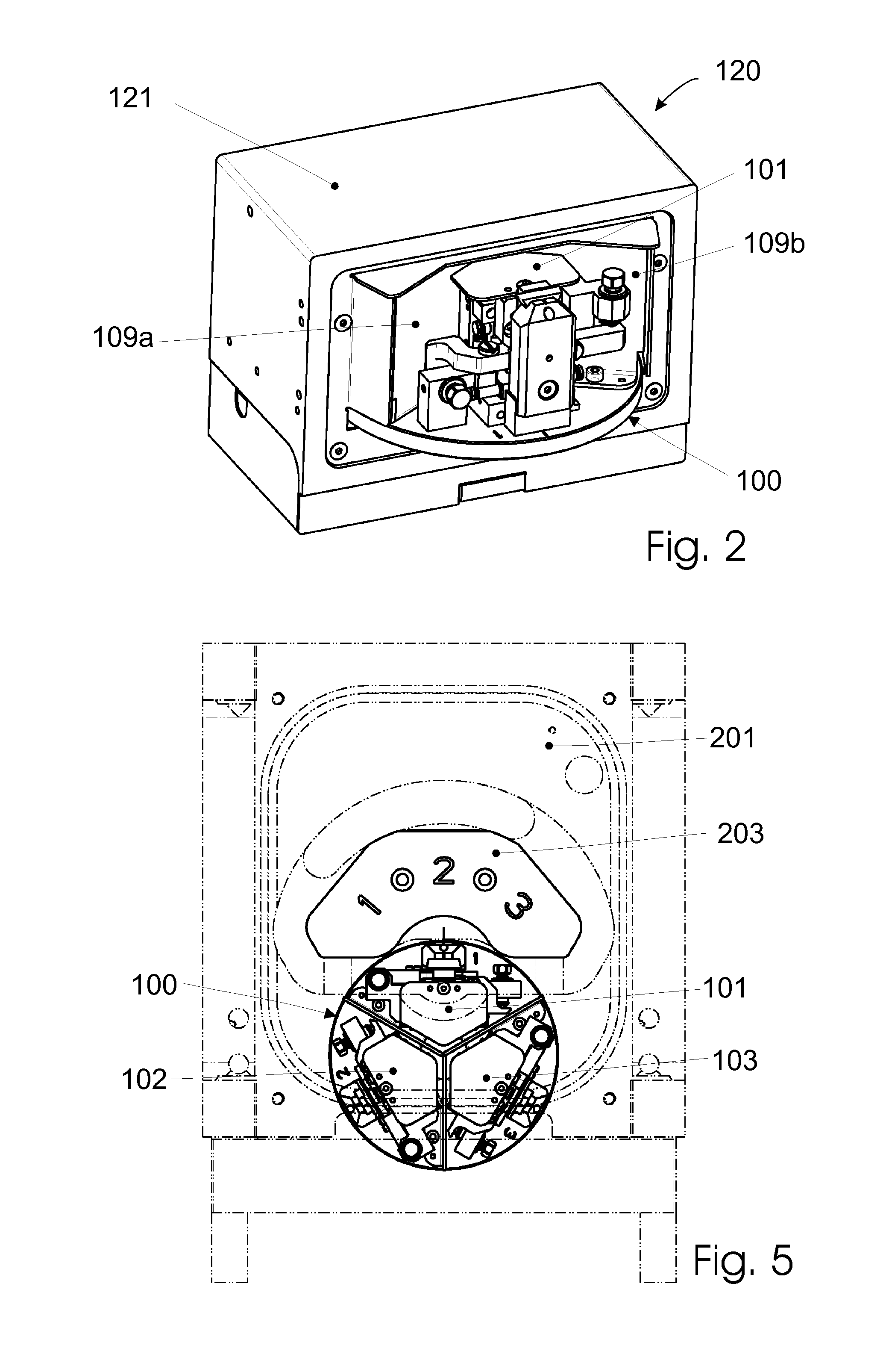
[0044]FIG. 1 shows the invention in the form of a rotatable sample stage 100 for an ion beam etching unit, which stage is mounted rotatably around a vertical rotation axis L (horizontal turntable). The sample stage encompasses a turntable 107 on which a total of three positioning arrangements 101, 102, 103 are arranged at an angular offset of 120° from one another. The configuration of the individual positioning arrangements 101, 102, 103 is known per se to one skilled in the art, and is designed for an ion beam slope etching method as one described in WO 2008 / 106815 A2. Each positioning arrangement 101, 102, 103 encompasses a receiving apparatus 106, adjustable in two planes, on which a sample 104 can be mounted, as well as a mask holder 108 having a mask 105. Arranged between each of the three positioning arrangements 101, 102, 103 is a protective divider 109a, 109b, 109c in the form of a metal protective panel, arranged perpendicular to turntable 107 and extending radially with r...

second embodiment

[0048]FIG. 6 is a plan view of a rotatable sample stage 300 that, like sample stage 100, is likewise embodied as a carousel-like horizontal turntable having a vertical rotation axis, but that comprises a plurality of positioning arrangements (301, 302, 303, 304, 305 . . . n) offset at identical angles from one another and arranged on a turntable 307. For example, up to ten positioning arrangements can be arranged on turntable 307 (n≦10), since sample stage 300 in that way, despite high capacity utilization of the ion beam etching unit, has manageable dimensions, and the necessary maintenance intervals, for example for the ion source, can be adhered to. The positioning arrangements of sample stage 300 correspond in principle, in terms of their configuration, to positioning arrangements 101, 102, 103 described above. Positioning arrangement 301 is located in the processing position, while the remaining positioning arrangements are in the waiting position. For rotation of the sample st...

third embodiment

[0049]FIG. 7 is a side view of a rotatable sample stage 400 that is embodied as a turret-like vertical turntable having a horizontal rotation axis. Sample stage 400 comprises a plurality of positioning arrangements (401, 402, 403, 404, 405, . . . n) offset at identical angles from one another and arranged on a turntable 307. For example, up to ten positioning arrangements can be arranged on turntable 407 (n≦10), since in that way the sample stage, despite high capacity utilization of the ion beam etching unit, has manageable dimensions, and the necessary maintenance intervals, for example for the ion source, can be adhered to. The positioning arrangements of sample stage 400 correspond in principle, in terms of their configuration, to positioning arrangements 101, 102, 103 described above. Positioning arrangement 401 is located in the processing position, while the remaining positioning arrangements are in the waiting position. For rotation of the sample stage 400, the latter likewi...


PUM

PropertyMeasurementUnit
rotationaaaaaaaaaa
pressureaaaaaaaaaa
acceleration voltageaaaaaaaaaa

Abstract

A sample stage for processing a sample in an ion beam etching apparatus has positioning arrangements each having a receiving apparatus and a mask, a sample being mountable in the receiving apparatus with reference to an ion beam and positionable relative to the mask. The sample stage includes a mechanism that enables a switchover between respective positioning arrangements so a selected positioning arrangement is respectively orientable toward the ion beam. The sample in the selected positioning arrangement is exposed to the ion beam while the remaining positioning arrangements face away from the ion beam. The positioning arrangements are arranged in one common vessel. A method for sequential preparation of at least two samples in an ion beam etching unit using the sample stage is also disclosed.

Description

CROSS REFERENCE TO RELATED APPLICATIONS[0001]This application claims priority of Austrian patent application number A 168 / 2011 filed Feb. 9, 2011, the entire disclosure of which is incorporated by reference herein.FIELD OF THE INVENTION[0002]The invention relates to a sample stage for processing a sample in an ion beam etching apparatus, having at least one positioning arrangement that comprises a receiving apparatus and a mask, a sample being mountable in the receiving apparatus with reference to an ion beam that is directed toward the sample stage during an ion beam etching operation, and the sample being positionable in terms of its position relative to the mask.[0003]The invention further relates to a method for sample preparation in an ion beam etching unit.BACKGROUND OF THE INVENTION[0004]Ion beam etching is a method often utilized to prepare samples whose structure is then typically investigated by scanning electron microscopy (SEM) and transmission electron microscopy (TEM)....

Claims


Application Information

Patent Timeline
Patent Type & Authority Applications(United States)
IPC IPC(8): B44C1/22
CPCH01J37/30G01N1/32C04B35/80
Inventor PFEIFER, THOMASPLANK, HEINZ
Owner LEICA MICROSYSTEMS GMBH
Why Eureka
Try Eureka