Spiral Wire Retaining Device and Method of Using the Same

a technology of spiral wire and retaining device, which is applied in the direction of suspension device, application, surgical instrument support, etc., can solve the problems of difficult management of the spiral wire end portion, and achieve the effects of convenient inserting and removal, simple and secure, and ease of loading

Inactive Publication Date: 2012-08-09
TAYLOR KEVIN D
View PDF7 Cites 1 Cited by
  • Summary
  • Abstract
  • Description
  • Claims
  • Application Information

AI Technical Summary

Benefits of technology

[0010]An advantage of the invention is to provide an apparatus to securely retain a medical wire to a medical surface while providing ease of loading and removal of the medical wire from the apparatus.
[0011]Another advantage of the invention is to provide a simple and secure means for attaching the apparatus to a medical surface.
[0012]Another advantage of the invention is to provide a retention device that allows guidewire and catheter exchanges through it without having to remove the guidewire or catheter from the retention device.
[0013]Yet another advantage of the invention is to provide an apparatus that is configured to be easy to insert, remove, securely retain medical devices, and secure to the various surfaces encountered during medical procedures. Moreover, the apparatus is configured to allow for the insertion and withdrawal of catheters over retained guidewires during interventional procedures. Thereby, removing the guidewire from the retaining device during a catheter removal or insertion prevents additional risk that the guidewire might fall from the procedural area and become contaminated. It also allows for placement of the retaining device further from the catheter insertion point, thus adding more support where it is needed, near the end of the guidewire. In one embodiment, the spiral or helical holder structure also has advantages over other structures in that it has a low profile or high ratio of holder area to device diameter.

Problems solved by technology

This trailing end portion can be difficult to manage and requires special attention from the medical staff to ensure it does not become contaminated, tangled or confused with other wires in the procedural area.

Method used


Image

  • Spiral Wire Retaining Device and Method of Using the Same
  • Spiral Wire Retaining Device and Method of Using the Same
  • Spiral Wire Retaining Device and Method of Using the Same

Examples


example 1

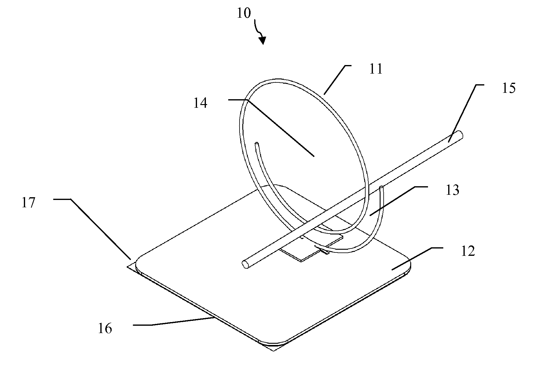
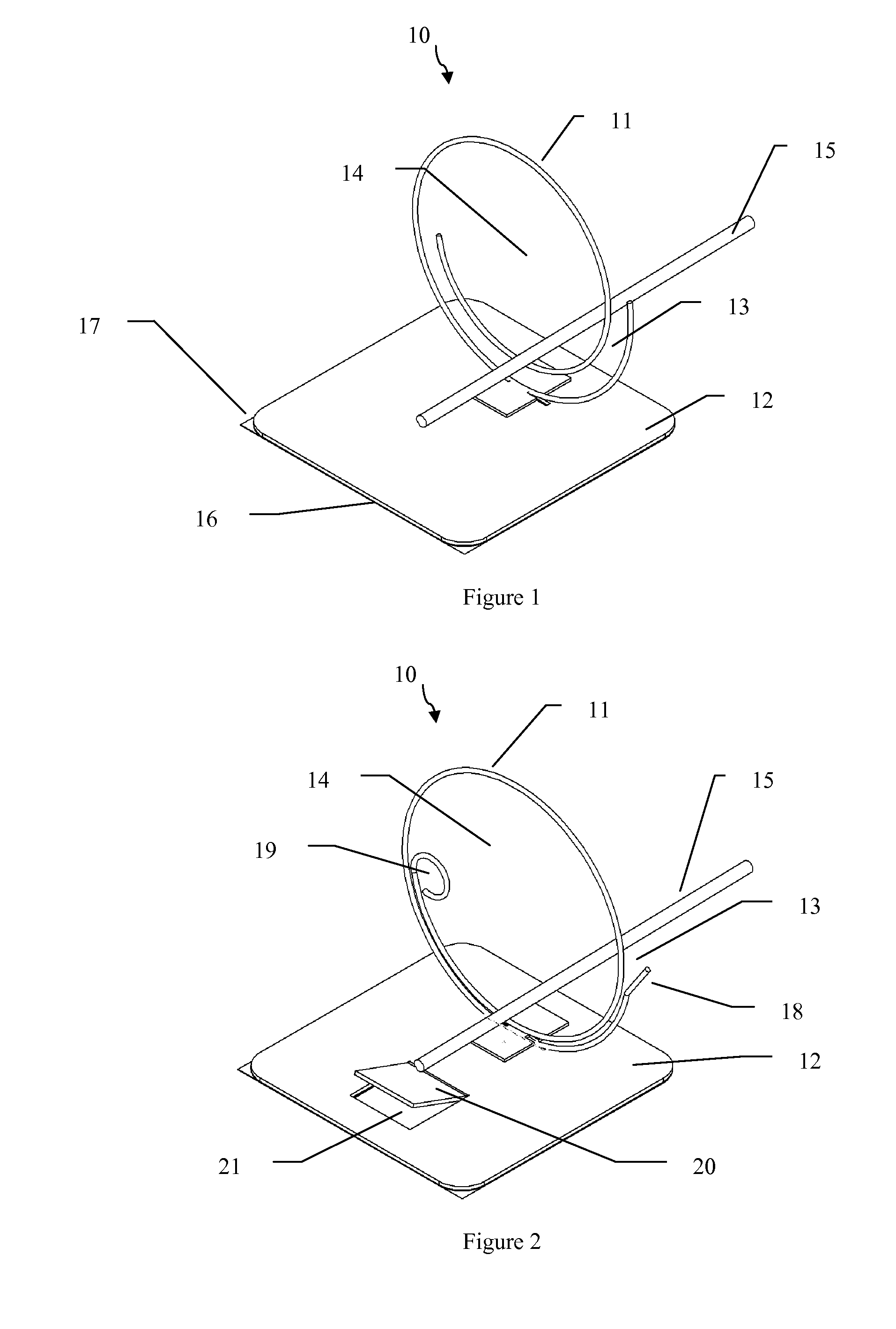
[0054]In this example, a spiral holder portion was fabricated to the shape similar to that shown in FIG. 2. A stainless steel wire having a 0.045 diameter, a 304 spring temper was formed with a CNC machine. The inner most diameter is about 2.5 inches and the spiral winds to the outside with a 0.14 pitch for 1.4 revolutions. The inner most terminal end of the wire is formed to about 0.4 inches in diameter circle and 0.5 inches of the outer most terminal end is bent outwardly 20 degrees as shown in FIG. 2.

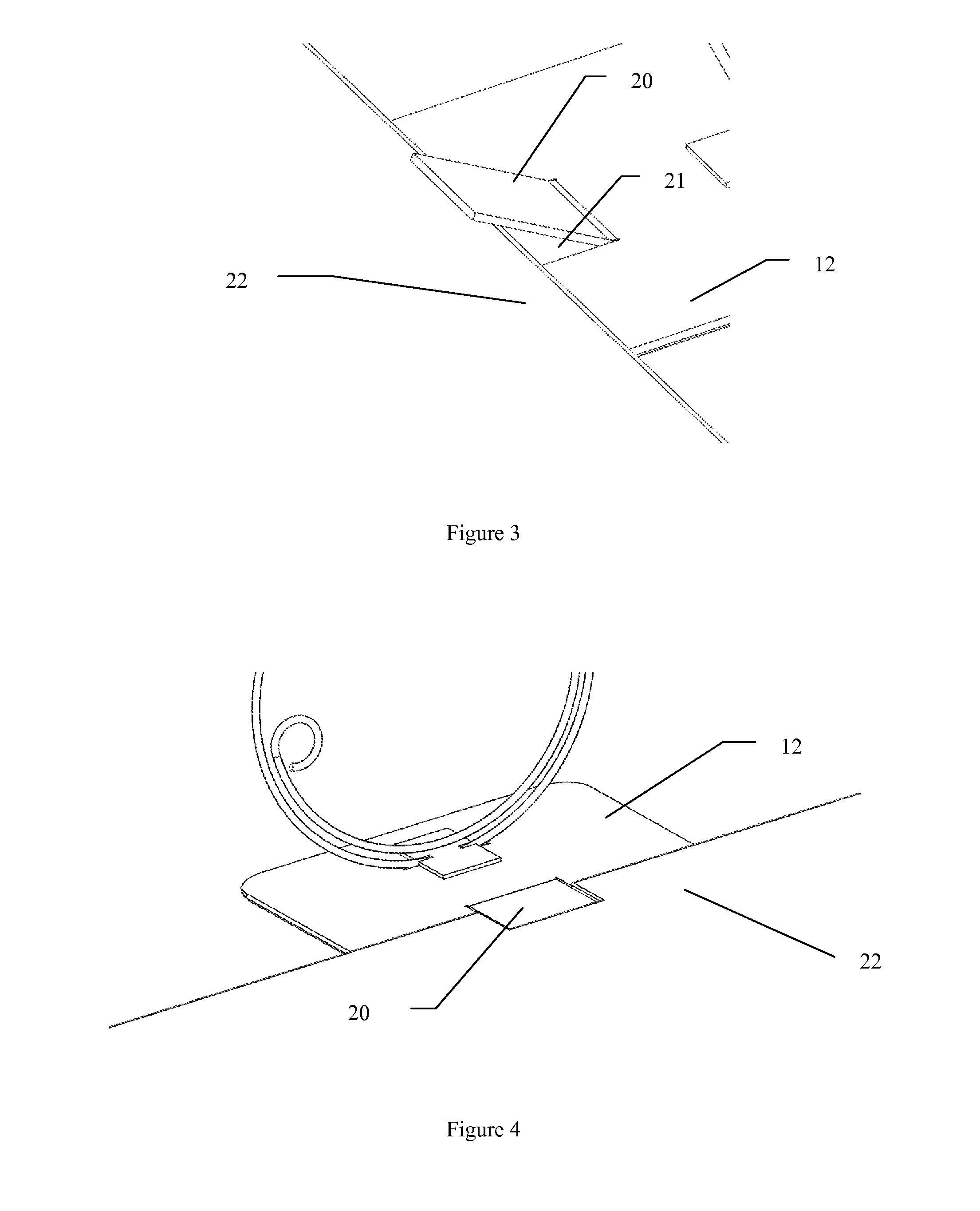
[0055]The base was formed by cutting a 0.125 inch thick neoprene pad to a 5×7 inch shape. A bracket for attaching spiral holder portion to base was formed by cutting a 0.04 thick polyethylene terephthalate glycol (PETG) sheet material to about 1.4×1.4 inch in size. Two slots, measuring about 0.05 inch wide by 0.25 inch long are cut in the center of two opposite sides of the bracket as shown in FIG. 2. The bracket was placed along the outermost spiral between the terminal ends of the ...


PUM


Abstract

A retaining device for retaining at least one medical line adjacent to a supporting surface comprising a spiral-shaped holding portion defining a peripheral edge, loading channel and internal holding area, the internal holding area dimensioned to accept the largest medical wire the device is destined to be used with; and attachment means connected to a holding portion to secure the retaining device to a supporting surface; wherein a section of medical wire may be inserted into and along the loading channel to enter the holding area and be retained within.

Description

[0001]This application claims the benefit of U.S. Provisional Patent Application No. 61 / 440,245, filed on Feb. 7, 2011, which is hereby incorporated by reference for all purposes as if fully set forth herein.BACKGROUND OF THE INVENTION[0002]1. Field of the Invention[0003]The invention relates to spiral wire retaining devices and, more specifically, spiral wire retaining devices for securing medical wires, catheters, guidewires, electrical lines, tubing, cables, and other elongated members.[0004]2. Discussion of the Related Art[0005]Guidewires and catheters are used in a variety of different medical procedures, such as, during angiographic, endovascular, or surgical procedures. Guidewires are typically used to position catheters in a body lumen, for example, arteries, veins or natural orifices within a mammal. The leading end portion of the guidewire is typically introduced into the body through an incision or natural orifice and then advanced to the treatment area. A catheter can be...

Claims


Application Information

Patent Timeline
Patent Type & Authority Applications(United States)
IPC IPC(8): A61B19/00F16L3/08
CPCF16L3/1222A61B19/26A61B90/50
Inventor TAYLOR, KEVIN D.
Owner TAYLOR KEVIN D
Why Eureka
Try Eureka